Quantcast
Channel: Moates Support
Viewing all 191 articles
Browse latest View live

88-93 Holden VN + VP Commodore 1227808

$
0
0

Introduction

The 88-93 VR Commodores use the 1227808 ECM which is basically the same as a US 1227165 ECM that is limited by hardware to 160 Baud communications.  These ECMs have torque converter lockup control as required for a 700R4 or similar automatic transmission.

Hardware Required for Tuning

  • G1 Chip adapter and C2 27SF512 chip required to reprogram ECM
  • BURN2 Chip Programmer programs 27SF512 chips
  • ALDU1 with CABL1 required for datalogging
  • Ostrich2 required for real time tuning
  • APU1 AutoPROM All-in-one device works great, taking the place of BURN2, ALDU1+CABL1 and Ostrich2

Software Required for Tuning

These computers use the $5D, $A5, $B1, $DB, $FB or $03 masks.

TunerPro RT has editing definitions on the website for $5D, $A5 and $FB

 PCMHacking.net appears to have datalogging definitions for TunerPro RT.

TunerCat OBD1 tuner has editing definitions available for $5D, $A5, $B1, $DB and $FB


94-95 (ish) Mass-Air trucks with E40D Electronic Transmission VEX1 WAY1 HOG0

$
0
0

Introduction

94-95 MAF Trucks are an interesting breed.  They feature sequential fuel injection, a distributor for spark delivery, Mass-air flow (MAF) sensors for air metering and most importantly are set up to control an E4OD electronically-controlled automatic transmission.  Aside from their original application, these ECMs are commonly used for speed density->MAF conversions on speed density trucks and Broncos that had E4OD transmissions.   With little more than programming, they can use used to run everything from a 460cid big block (or larger) to a simple 302 or a 5.8L Windsor engine.

Hardware for Tuning

  • QuarterHorse – integrated device brings unique functionality to the table.  It is a “chip on steroids” that allows you to make changes while the vehicle is running and (with supporting software) log live data from the vehicle.  Any tunes developed using a QuarterHorse can be programmed to F3/F8 chips for long term use.
  • F3 – simple chip module that can store one or two tunes and switch between them while vehicle is running.  Requires Jaybird programmer or BURN2+FA.
  • F8 – fancy chip module that can store eight tunes and switch between them while vehicle is running.   Can also be programmed while installed – no need to remove chip to reprogram it.  Requires Destiny programmer
  • BURN2 + FA + FE – generic chip programmer with Ford adapter (FA) and ECM interface (FE) that can be used to read the current program from EECIV and EECV ECMs on the bench.

Software for Tuning

The AHACB strategy is used on these ECMs.  Both Binary Editor and EEC Editor support editing this strategy.  Only Binary Editor supports datalogging at this time.  It does not make sense to buy a QuarterHorse unless you’re also willing to buy Binary Editor and one of the available strategies for it.

  • Binary Editor ($100 – $171 available from Moates.net) is a Ford-specific graphically oriented tuning software that supports many EEC-IV and EEC-V processors.  There are several options for BE2012:
    • EEC Analyzer ($50 available from Moates.net) is an optional companion program to Binary Editor to assist with analyzing data and automating tuning tasks.
    • The optional dongle for Binary Editor allows you to use the software on more than one laptop instead of being locked to a single machine.($+71)
    • Core Tuning definition ($195 available through Coretuning.Net or ben@coretuning.net ) – uses same standards for organization as other Core Tuning defs, very complete, includes full datalogging.
    • Derek Fenwick’s AHACB definition ($25, contact sailorbob@uk2.net ) supports these ECMs.  Usually complete and extremely functional.
  • EEC Editor ($20 available from Moates.net) has basic editing support for the these ECMs.  EEC Editor is a basic application for tuning Fords.  There is no logging support at this time. (1/2015)

Recommended Combinations

Looking at what’s available, there are 3 1/2 combinations that make sense:

  1. EEC Editor ($20), Jaybird ($75), F3 ($60)
    Option 1 gives you the cheapest way to tune your WAY1.  You will NOT have logging – just editing.  You will NOT have realtime tuning – you’ll have to shut down, program chip, reinstall chip each time.  EEC Editor is a very basic application without many graphics or frills but it’s mostly functional as an editor.  (you can download it and check it out from the Tuning Software section of our website)
  2.  QuarterHorse ($249), Binary Editor ($100) with Derek Fenwick definition ($25) and optionally dongle for BE ($+71) and optionally Jaybird+F3
    Binary Editor is better software.  Derek generally makes very good definitions.  The combination of QH + BE + Def is going to give you realtime tuning while the vehicle is running AND datalogging to see engine and transmission parameters.  It’s still a good idea to have a chip for long-term use but chip tuning hardware is optional, at least from a getting started perspective.
  3. QuarterHorse ($249), Binary Editor with dongle($171) with Core Tuning definition ($195) and optionally Jaybird+F3
    Option 3 is somewhat similar to #2 except the dongle is REQUIRED for Core Defs.  Core Tuning definitions are generally really well laid out, well defined and have a large selection of parameters to choose from.  They’re a US company with great support.  Again, chip tuning hardware is optional but recommended.

Note: I’ve not seen either Derek nor Core’s defs personally so I can’t give you a meaningful comparison between the two.

The “half combo” I refer to is including the chipping tools (Jaybird+F3) as well as the QH in #2 and #3 above.

Roadrunner: Hard Resets

$
0
0

When you set up a Roadrunner in a vehicle, you will often need to force a ‘hard reset’ of the Roadrunner PCM. This is particularly true if you are using a custom OS or changing OS type.

For using EFI Live, perform the following:

  1. Open up the software, and get the EFI Live Roadrunner Control Panel. Make sure the Roadrunner serial number is being displayed.
  2. Upload the whole new Operating System and Calibration from the PC *.tun file to the Roadrunner device.
  3. Select the “Execute from PCM Flash Memory (if equipped)” option (two chips with arrows in between). This will turn the Roadrunner emulation ‘off’ in order to blank out the PCM RAM when the memory read faults. The software should display ‘Flash’ as the mode of operation.
  4. Re-select the button, this time selecting the ‘Emulation’ mode of operation.
  5. Turn the key or power to the PCM off, wait 10 seconds, and turn it back on.
  6. If you like, at this point you can open the EFI Live ScanTool software (make sure cable is connected and vehicle is on). You will probably want to scan for codes and DTCs, and clear them all as appropriate.
  7. Start the vehicle briefly (1-2 seconds) and then shut power back off. This is primarily to reset the idle relearn, so it typically not an issue with the drive-by-wire configurations.
  8. You should now be able to restart the PCM and vehicle, and things should work as expected if you are using a valid *.tun file.

This procedure will also help if you have suffered tune corruption.

If you have any questions, contact EFI Live or Moates technical support and they’ll be glad to help further.

Emulation Cables

$
0
0

Introduction

Emulation cables link our emulators to a target device.  The Ostrich, Ostrich2 and APU1 all use a similar style emulation cable.  The design of this cable has not changed in many years.  Four standard “shelf” cables are available:

  • EMUC2818 is the standard cable supplied with the Ostrich, Ostrich2 and APU1 emulators.  It has a 28 pin chip side (“28″) and is 18″ long (“18″) hence EMUC2818
  • EMUC2806 is a shorter cable (6″) with a 28 pin chip socket.  It is useful for situations where there is interference with the standard length cable.
  • EMUC3206 is a short (6″) cable with a 32 pin chip socket.  When used with an Ostrich2 it allows emulation of a 29F040 4Mbit EPROM.  Adapters can be used to change this to PLCC or other formats.  This cable is NOT compatible with the Ostrich 1, APU1 or ChipExtender – Ostrich2 ONLY!
  • EMUC2836 is an extra-long (36″) cable with a 28 pin chip socket.  It is NOT for use with emulators.  This cable is only intended to be used with the ChipExtender product we sell.  Unpredictable results can happen when used with emulators.

The RoadRunner uses an alternative emulation cable which is incompatible with other devices.


Ostrich and APU1 Emulation cables

The Ostrich, Ostrich 2 and APU1 all use the same emulation cables.  These cables have a 0.1″ pitch rectangular connector on one end.  On the other end, a male chip connector is crimped.  Before shipping the cable, we install a machined-pin socket on the cable to protect the more fragile chip connector.

This is how one of the cables looks when we ship it:

emuc_assembled

As you can see, you can remove the 28 pin machined-pin socket on this cable if necessary:

emuc_apart

Replacing a MP socket is much easier and cheaper than replacing a whole emulation cable!


RoadRunner Emulation cables

The roadrunner uses unique cables designed to connect RR hardware with a soldered-on POSOP44 pin header.  Typically, two of these cables must be connected back-to-back for proper operation.

More will follow.

Ford EFI Tuning Class – March 2015 Baton Rouge, LA

$
0
0

Learn to Tune Fords in Comfort!

We are going to be offering a three-day class on tuning Fords with QuarterHorse in March 2015 – weekend of 3/28/15.  Come enjoy Baton Rouge before it gets too hot to be fun!  Classroom instruction will take place in the Moates Event Center around the corner from Moates HQ.  Street tuning and dyno instruction will take place on a Mustang dyno in the area.  The exact format of this class will be determined by the abilities and interests of the attendees.  Previously, we have spent a lot of time on general tuning theory, Ford EECIV operation and then hands on work.  This time, all bets are off.  EECV, automatic transmissions and transmission tuning, hands-on forced induction vehicle tuning are all options that will be determined by surveying attendees prior to class.

Cost

Registration for the class will be $350.   You can pay with any of the methods that we accept on the website (Paypal, Credit Card) in advance or pay cash/money order at the door.  If you’re going to pay at the door, we ask that you purchase the class item from our website and select “Check or Money order” at checkout so we can keep an accurate headcount and reserve your spot.  All of the products that are used for the class will be available for purchase at/after the event at a discount for attendees. You can register for the event here.

Class Overview

Dave Blundell, Moates tech support and former tuner at Modular Depot will be the instructor.   Craig Moates, founder and engineer of Moates products will give an in depth overview of hardware.

Registration will be limited to 12 people in order to keep the class manageable and give everyone a chance to get involved and ask questions.  There will be a mixture of classroom instruction, live in-car demonstration of logging techniques with street driving and dyno tuning and techniques.  Forced induction and naturally aspirated modifications and tuning will be covered.  We expect lots of discussion and have built time for this into the class schedule.

Traditonally, primary focus will be on 89-95 (i.e. Fox-body Mustang, 94-95 Mustang) EEC-IV MAF Fords but much of the material will carry to later models also supported by the same hardware and software.  This class is aimed at beginner-intermediate users, but those with literally no experience at all may want to look at some of the material in advance in order to be better prepared.  Likewise, if you have years of experience with Ford EFI tuning and you’re simply looking to get familiar with using our products for the EEC-IV platform, you should already be familiar with some of the material presented.  We cover everything from physical engine operation to air metering methods to Ford implementations with a goal of helping you make targeted tuning changes and not just “button mashing.”  As previously stated – we’re going to let student interest dictate the exact path class takes.

Schedule of Events

Assuming we run this class like previous classes, the following schedule will apply.  If students elect to focus on more advanced topics, we will adjust the schedule accordingly. (And there may be homework prior to class!)  One thing is for certain – we only have three days.

Day 1 (3/27) will focus on general theory of how engines work, how electronic engine management works and general approaches to calibration of engine management systems.  Chances are, if you’ve been tuning cars for five years you probably already know a lot of this stuff but it probably wouldn’t hurt you to sit through it again.  If you’re new to engine management, expect your brain to hurt.  The goal of day one is to help you understand how the many pieces of engines, electronics and sensors that you will be dealing with fit together – the big picture.  Most of this day will NOT deal with Ford specific terms and methods.  At the end of the day, you should have a strong understanding of spark ignition internal combustion engines, how and why engines make power, be able to name and explain the function of sensors likely to be found on a fuel injected engine and understand the conditions needed for achieving specific goals such as fuel economy, power or keeping and engine in one piece.  If you’ve previously worked with other systems of engine management, you might look at what you already know in a new light.

Day 2 (3/28) will focus on early Ford engine management.  If you need to get any software set up and configured, we’ll take care of it on this day.  The morning session will focus on Ford specific terms and procedures for running an engine.  The emphasis will be on the most common and important parameters necessary for adjustment.   Fuel, spark, idle and limits will be covered as well as some of the limitations and pitfalls of using factory computers.  Both forced induction and naturally aspirated setups will be discussed.  After lunch, we will demonstrate setting up Moates hardware and how TunerPro RT and Binary Editor 2012 software can be used to make adjustments necessary for tuning Ford vehicles.   At the end of day two, you will have an understanding of the terms used in Ford EFI, be able to pick out the most important items that you need to change in a calibration when tuning and see how software can be used with Moates tools to tune vehicles.  GUFB (aka 89-93 MAF Fox Body Mustangs) and CBAZA (aka 94-95 Mustangs) will be the focus of this day.

Day 3 (3/29) will focus on hands-on usage of TPRT and BE, acquiring data from street and dyno use, analyzing it, diagnosing issues and making changes to tune your vehicle.  We will be acquiring data on the street and on the dyno and using it to make targeted changes.   This will be putting the theory from previous days together with real vehicles and seeing how to apply our understanding of Ford MAF systems to achieve results.  At the end of day three, you will be able to understand enough of Ford EFI systems and the software available to work with Moates tools to be able to acquire data and make precise changes based on measurements rather than simply “mashing buttons” to get results.

Plan on 8-10 hours of being focused per day.  We’ll typically run on a 9ish-6ish kind of day depending on how things go.  (Local time is Central Standard Time – CST)

There will be lunch, snacks and drinks provided.  At previous classes, we had an optional group dinner afterwards that worked out well.  Some of the best discussion ended up coming up over dinner, so we’ll do that again.

We’ll try to have a good chunk of the curriculum up here on the support site prior to the class for you to review and prepare.  You can also expect emails from us regarding the class and materials, so please make sure we have the correct contact information for you when you register.

Travel Information

There will be a limited number of spots available at the Moates event center where we are having the class.  There is no charge to stay at the event center but space is strictly first-come-first-serve.  Contact us via phone or email to reserve your spot.

Information on regional hotels is available on request.

Other Class Opportunities

Check out the support site for other opportunities to take a class on using Moates products.

92-95 Civic and 93-95 Integra 37820-P05 P06 P08 P28 P29 P30 P72 P74 P75 PR4

$
0
0

Introduction

If you are too lazy to read this whole page, you can skip to the “Recommended Combos” section at the end for a shopping list without any explanation.

92-95 Civic and 92-95 Integras are a common hardware platform – there is no sense in addressing specific vehicle or ECU models.  These ECUs are also a more or less plug-n-play substitute for 92-95 Accord and Prelude computers, which have not been figured out to the same extent.  96-00/01 OBD2 vehicles can also use ECUs on this page with an OBD2-OBD1 conversion harness.

Once chipped, these ECUs have many hardware options for tuning ranging from simple chip tuning to realtime options with integrated logging.  To learn about the different options, see “Tuning Hardware” below.

While there are differences between OBD1 Civic and Integra ECUs (Vtec vs. non-Vtec, manual vs. automatic, 1wire vs. 4wire O2 vs. 5wire wideband, power steering vs no PS, etc.) it is possible to convert any ECU that is a member of the “family” into any other ECU by a combination of modifications to the the circuitry in terms of adding and removing parts along with chipping the ECU to change its program.  The only “oddballs” are the 92-95 Civic VX P07 (which came from the factory with a wideband and was heavily optimized for fuel economy) and the 94-95 JDM GSR Automatic P72 (which is more like a OBD2 ECU inside.   Manual P72 ECUs are ok).  To find out more about various kits for converting ECUs or adding features see “ECU Modification Hardware” below.

The firmware of these ECUs has been hacked apart.  There are several software tools available for tuning this platform.  Many software tools extend the original capabilities of the factory computer, allowing forced induction, ITBs and larger injectors to be calibrated.  For more information about the software tools available, see “Software Options” below.

Tuning Hardware

  • Honda Chip Kit allows ECUs to be chipped
  • BURN2 programs C2 27SF512 chips which can be installed in chipped ECUs
  • Ostrich2 allows realtime tuning in chipped ECUs
  • Xtreme HULOG allows logging of data from ECUs suitably equipped
  • Demon1 allows realtime tuning (like Ostrich) logging (like HULOG) and also has onboard memory for recording datalogs without a laptop connected.  Honda Chip Kit is included.  Supports both JDM and USDM ECUs
  • Demon2 is an evolution of the Demon1 with non-volatile memory for program storage, more onboard memory and different connection options.  Honda Chip Kit is included.  Supports only USDM ECUs
  • Demon+Neptune combo is a Demon1/2 bundled with a license for NeptuneRTP software
  • Neptune License allows Demon users to upgrade to Neptune RTP software
  • Honda Tuning kit bundles a Honda Chip Kit, BURN2, Ostrich2, HULOG together
  • Engine Sim generates signals like an engine to allow testing of ECUs on bench

ECU Modification Hardware

  • Honda Chip Kit allows ECUs to be chipped
  • VTEC-1720 kit allows non-vtec ECUs with 1720 motherboard to be converted to run Vtec engines
  • VTEC-11F0 kit allows non-vtec ECUs with 11F0 motherboard to be converted to run Vtec engines
  • VTEC-1980 kit allows non-vtec ECUs with 1980 motherboard to be converted to run Vtec engines
  • PWM components kit adds the ability to control a boost control solenoid with supported software
  • Bluetooth modules allow wireless communication between laptops/smartphones and your ECU (Software support required for optimal operation.  Many applications that work with a HULOG will NOT run smoothly without modification)

Software Options

Looking at software options for this platform that work with our hardware, there are basically two choices:

  • Neptune – mature, stable, feature packed, well documented, bug-free
  • CROME – unstable, less features, non-existent documentation, lots of bugs

Neptune RTP is the version of Neptune we sell.  We HIGHLY recommend this option.  When you buy a Neptune License, it is married to a specific Demon hardware unit (Demon+Neptune package – $395), the license is paired with the Demon hardware unit.  You can use it on whichever laptops you want, but only hardware that has been licensed.  Neptune RTP allows you to tune, datalog and also set up onboard logging, i.e. logging without a laptop.  Advanced features ranging from wideband closed-loop to programmable output control for nitrous or otherwise are supported.  Multiple tunes can be selected.  Alpha-N (TPS maps) are possible for ITBs or large cam cars.  Boost control via PWM solenoid or multiple stages of solenoids is possible.  Neptune is mature, relatively easy to use, well-documented, feature rich, works as documented and relatively bug free.  TL;DR: You get what you pay for.   More info can be found an a demo version of the software can be found here.

We do NOT sell the dealer version of Neptune.  You can contact info@hrtuning.com for more information on this.

CROME comes in several versions.

  • The free version of CROME supports editing bins ONLY.  There is no logging.  There is no “Gold” ROM support.
  • The Pro version of CROME (available from Xenocron.com, $150) supports editing bins AND datalogging.  The “Gold” ROM can be used on a restricted basis.  This is intended for individual use only but the license is widely abused.
  • The Dealer version of CROME (available direct from CROME’s author only, $450?) supports editing bins AND datalogging.  It has full support for the “Gold” ROM.  Commercial users are meant to use this version.

CROME is a semi-community supported application.  (i.e. get your help on pgmfi.org) The software package itself is free to use for editing bins but any logging requires a paid version.  The “Pro” version intended for single user use is widely abused for tuning multiple cars.  CROME does NOT support the onboard logging or extra channels present on the Demon hardware.  CROME Pro/dealer will work with either the Demon as a in unit or with the Ostrich, BURN2 and HULog for chip-burning operation.  There is no documentation for CROME, aside from what is available from the community.  There are many things that are not working properly and tons that are mislabeled or misrepresented – individual cylinder trims, startup enrichment corrections and vtec pressure code elimination (among others) are all problematic as of February 2015.  CROME is the cheapest way to get into tuning Hondas but it hasn’t kept up with the support and features offered by Neptune.  We do NOT sell CROME – you can purchase Crome Pro from xenocron.com or CROME Dealer from tunewithcrome.com

Recommended Combos

For the end user looking to tune their own car with ease, there is only one good choice: the Demon+Neptune kit offers a comprehensive package of everything required to chip and tune an OBD1 Honda ECU in a convenient package.  The best hardware and best software combine to provide the best tuning option, hands down.  But it’s not cheap if you’re looking to do a fleet of vehicles.

For the aspiring t00ner on a budget looking to tune every car in their neighborhood, there is only one good choice: the Honda Tuning Kit paired with a CROME Pro/Dealer license sold elsewhere and a dozen Honda Chip Kits.  No other option will let you tune as many cars for the money.

Combos to Avoid

The Demon is only fully supported by Neptune RTP.  You can purchase an Ostrich and HULOG for less than the price of a Demon.  It does not make sense to buy a Demon if you are planning to use CROME.

The Honda Tuning Kit, BURN2 and Ostrich2 are NOT supported by NeptuneRTP.  In order to use these devices with Neptune, you must sign up as a dealer for Neptune – something we do not get involved with.

RMA Procedure

$
0
0

Intro

Although we do our best to test things before shipping them to you, things happen.  And sometimes those things mean that the devices you order from us just don’t work.  In other cases, devices quit functioning after a time of faithful service.  We understand this and we’re generally very willing to get you a replacement.

What we ask of you:

  1. CONTACT US FOR HELP.  Don’t just send something in.  Contact us via phone support or email first.  Give us a chance to help you resolve the issue without sending things back.  A substantial portion (well over half for certain products) of items returned to us test fine and pass testing.  We would love to be able to help you resolve those errors so that you don’t have the same problem with two good units.
  2. Be honest.  If you tell us your car caught fire (yes, this has really happened) or your dog chewed it (yes, again true) or your car flooded (yes, again true) we will probably chuckle and help you.  If you lie about what happened and we figure it out, we’ll probably be pissed and much less likely to help you
  3. Be descriptive.  When you follow the RMA instructions (see below), you will be asked to explain the problem.  We expect more than, “It don’t work.”  Instead, we would hope to see something more like, “I have a Windows 8.1 laptop.  I plugged my BURN2 in, had drivers installed correctly but the Flash n Burn software did not find my device.  I contacted support and worked with them to diagnose the issue.  They recommended that I RMA the device.”

Please try to follow RMA procedure!  (detailed below)  If you don’t do this, we’re not going to know what to do when your item shows up.  If you ship us something BEFORE making an RMA order, please fill one out as soon as possible and include a note that you shipped your RMA without properly marking the box.

We offer two options for warranty service:

  • “Standard RMA” : send defective goods in, wait for them to arrive and get checked out, we mail you replacements.  If you’re not in a hurry, this is the best option for you.  (See below for more)
  • “Express RMA” : purchase the replacements you need, choose your shipping method.  Replacements ship immediately.  Send defective goods in, wait for us to receive them, receive a refund for the order placed.   If you’re on a tight time schedule, this is the option for you.  Your order is essentially a refundable deposit to ensure you return the original goods.  (See below for more details)

Standard RMA Procedure

  1. Contact support.  Troubleshoot the issue.  If they determine you need replacements, continue.
  2. Go to the “RMA – Repair and Replace” section on the left navigation bar of our website.
  3. Add the Return Service item to your cart.  Check out.  You will be placing and order with us, just like if you were buying new goods – except there is no charge for RMAs.  (We do this to make sure we have the correct contact and shipping information for you and so you can track the status of your RMA.)
  4. During checkout, please explain in detail what is wrong and what you have done for troubleshooting in the “Comments” box.  Please explain which vehicle and ECU/ECM/PCM you’re using.  If you have any special requirements, this is your opportunity to be clear about what you need.  Finish the checkout process.  If you forgot anything, you can email us and reference your RMA number.
  5. You should receive an email from us at the address you used to register for our site with an order number for the RMA you just filled out.  If you do not receive this email, please check and make sure you have the correct email address in your profile.  As a backup, you should be able to see the RMA Order number in your order history while logged in to our site.  This order number will be your RMA number.
  6. Box the item up and send it to us with “RMA xxxxxxx” written clearly on the outside of the box.  You can find our address here: https://www.moates.net/info_pages.php?pages_id=6
  7. Wait for the item to arrive.  We do NOT typically update order status to indicate items have arrived.  If you have concerns, you may email us.
  8. RMA turnaround time varies according to how busy we are but is typically 5-10 business days from when we receive it till when a replacement ships.  If you’re in a hurry, you can email us and say “please” but we cannot guarantee the processing time for standard RMAs.  (see below if you are in a hurry)
  9. We will repair or replace the item at our sole discretion and ship it back to you.  We typically ship either UPS Ground or USPS Priority mail or domestic orders or USPS Express mail for international orders.  You will typically receive a tracking number when your replacement ships.


Express RMA Procedure

  1. Contact support.  Troubleshoot the issue.  If they determine you need replacements, continue.
  2. Place an order for the item(s) you need a replacement for.  If you have special requirements (switching headers, bluetooth headers, etc.), please be sure to mention them in the ‘Comments’ box otherwise “stock” replacements will be sent.  Double check your shipping address!!!  You can choose whatever method of shipping you need for replacements, including overnight shipping.  (Please remember we do NOT ship every day!  Express RMAs are no exception!)  We typically provide ground/priority shipping for free with standard RMAs.
  3. Check out.  You should receive an  email from us at the address you used to register for our site with an order number for the replacements you just ordered.  If you do not receive this email, please check and make sure you have the correct email address in your profile.  As a backup, you should be able to see the order in your order history while logged in to our site.  Please remember this order number.
  4. Follow the “Standard RMA” Procedure above.  In the ‘Comments’ box, explain that you already placed an Express RMA order for replacements and your order number is #xxxxx.  Explain you would like a REFUND for order #xxxxx.  This is critically important.  If you do not explain that you placed an Express Replacement order and ask for a refund, we will send you replacement parts and you will have two sets.
  5. After your defective goods arrive, we will process your order (again, 5-10 business days is standard turnaround time) and we will issue a full refund for the original goods purchased.  If you choose a more expensive shipping method than our “standard” shipping, you may receive a pro-rated refund instead of a full refund of expedited shipping costs.

RoadRunner and Bosch ME7

$
0
0

Lately, we’ve seen a lot of interest in using the RoadRunner as a general purpose ROM emulator for the Bosch ME7 platform as found in ~2000-2005ish Volkwagen 1.8t and Audi 2.7t applications.  This is an “off-label” application and you should NOT expect “plug and play” ease of installation.  This isn’t something that we’ve played with ourselves very much, so the information we can offer is somewhat limited.  This page will attempt to collect what we know in one place.

  • The 1024K RoadRunner Guts kit is the principal hardware being used.  We offer an install service but highly encourage you to do this yourself.
  • The main online forum where DIY-ish activity for this platform seems to be Nefarious Motorsports
  • People seem to be using mostly TunerPro RT (with a XDF from nefmoto) and WinOLS software.
  • There seems to be an endian difference between many of the ME7 files and the RR.  We sell a byteswap board (2.7t specific I think?) which can be used to correct this.  (Or it can be done in software)
  • There is a “bridge” program that allows the RR to be used with WinOLS:  Nefmoto forum link


Honda Tuning with Crome Tutorial

$
0
0
Honda Tuning with Crome
This is a very nice PDF tutorial written up by Darren Kattan. Check it out by clicking HERE.

HULOG/HondaLog Installation

$
0
0
Hulog/Hondalog
Installation of Honda-Based USB Datalogging Tools

There are two tools available for datalogging on Honda ECUs from www.moates.net and they include the HULOG and the HondaLog.

HULOG: The HULOG comes in a plastic enclosure and ONLY requires a pin swap if it is an older unit. All the new units come with 1:1 connector pinning, so will differ from the pictures shown in that no pin swap is required or will be present on the extension cable. It can be mounted externally or internally, depending on whether you want to pass the 4-pin header cable or a USB cable out of your ECU.

HondaLog: The HondaLog can be mounted directly to the ECU with no interconnecting cable It can also be mounted at the end of a 4-pin tether cable. Either way, no pin swap is required (note color of wires and their order in the pictures). The unit is shipped with two pinning options in terms of the attachment header. It also comes with a piece of shrink-wrap tubing in case you want to ‘wrap that rascal’ when you’re done. Either way, it goes to your USB cable and PC on the other end.

Pictures are shown below for the two units. The installation header is a 4-pin latching unit, and comes with the moates.net Honda Chipping Kits. You can alternatively use a 4-pin 0.025″ square-post breakaway header. Please take note of the directionality of the latch on the interconnecting cable though, since that is critical.

HULOG Pictures


HondaLog Pictures


Help We Provide

$
0
0

We aim to be as transparent as possible about EFI tuning and the products we sell, allowing you to make educated decisions.  You won’t call us up and have someone tell you it will be easy and you’ll have your crazy engine tuned in 30 minutes unless that really is the case.  You’re going to hear a more pessimistic account of what it would take because we think it is important for you to have realistic expectations.  EFI Tuning isn’t the kind of thing most folks can master in a few hours.  You’re not in it alone, however, as we are here to help.  This article will discuss what we do and don’t provide in terms of assistance.

We will:

  • Help troubleshoot startup issues such as drivers, software installation and physical connections needed
  • If necessary, provide remote computer control during phone support hours to get you to the point where you are connected and can log data and/or make changes, as appropriate
  • Answer SPECIFIC questions about how to tune your vehicle like “What do I need to change to raise my idle when in gear on my 93 Mustang?”
  • Look over a tune or datalog you send us for “sanity” – i.e. is there something obvious wrong
  • Try to direct you to resources such as forums or documentation available online to further answer any questions you may have when we don’t have answers

We will NOT:

  • Provide base tunes.  Everything we sell is blank.  If absolutely necessary, we can try to refer you to someone who can provide a ready-made tune for you.
  • Provide specific tune guidance. i.e. “You should try 20 degrees of timing.”
  • Provide extensive hand-holding, i.e. step-by-step tuning guidance
  • Answer vague or open-ended questions i.e. “How do I tune my car?”
  • Look over tunes or datalogs and tell you what to change.
  • Provide any assistance modifying or disabling emissions equipment

Honda Chipping Kit Install

$
0
0

This is Keebler65’s old guide. Some of the chipset and software info is a bit dated, but the techniques are good.

ECU Chipping

You need to add a few additional components to the original Honda ECU. It requires some soldering skills and should not be attempted unless you have soldered before. (Chances are you know someone with soldering skills that could help you). Here is a picture of the P28 ECU that I chipped, before any of the parts were put in:


Before you can solder the parts in, you will need to de-solder the holes in the circuit board since they come filled with solder from the factory. You can buy a “solder sucker” to do the job, however unless you get a nice one (expensive) they don’t really work well in my opinion. The cheap and easy solution is to buy some solder braid. It’s just braided copper. Simply place it over the hole to be de-soldered, and place the soldering iron on top of the braid. It will then wick up the solder into the braid. It’s available at radioshack:


You’ll want to use a decent quality soldering iron to get the job done nicely. The important thing is to not use too much heat, and also make sure the iron has a fine tip on it. I’m using a standard Weller iron:


Here is what it should look like after the board has been de-soldered:


The parts that need to be added are boxed in with a dashed white line. The parts consist of (2) .1uF ceramic capacitors, (1) 1k resistor, (1) wire jumper (simply a piece of wire…I used a lead of the resistor), (1) 74HC373 chip, and (1) 29C256 chip (thats the EPROM). The resistor and capacitors have no polarity, so you don’t have to worry about installing them backwards. The 74HC373 chip does have a polarity. Pin 1 will be on the left side of the pic (you’ll see in detail later one). The same is true for the EPROM chip. Since it would be impossible to burn a chip and have the tune be perfect, it becomes obvious that you don’t want to solder the chip in. Instead, use a socket so that it can be removed. You have two options: for less than $1, you can get a standard DIP socket. The problem is these are very hard to insert and remove the chips since there are 28 pins (it requires a lot of force and is hard to grip the chip). Your second option would be a ZIF (Zero Insertion Force) socket, which costs less than $10. It is a socket that has a lever: pull up the lever, set the chip in/lift it out, and flip the lever back – VERY nice to have since you’ll be doing this many times while tuning. Be careful when ordering the ZIF socket, as many of them are too large to fit on the board without running into things. The first ZIF I bought was made by Aries, and it was a very quality piece, however, it was too large and bulky to fit without a lot of modification to other components on the board. I ended up ordering a different one that was much more compact. I am unaware of the brand, however it is blue and is referred to as a low-profile ZIF. The only problem was that the lever end of it was in the way of the 74HC373. The easy solution is to buy a standard DIP socket as mentioned above. Solder this onto the board. Then, stack the ZIF onto this socket, which raises the ZIF away from the board enough to clear the surrounding parts. This setup worked very well for me. The following picture shows the too-big-to-fit ZIF in the back-left, the low-profile ZIF in the front left, and the DIP socket on the right:


The ZIF socket stacked on the DIP socket for added height:


And finally, a couple of pics with all of the parts installed:


I ordered most of my parts from www.jdr.com except for the low-profile ZIF socket and DIP socket, which I obtained from www.jameco.com. The following table containse the exact part numbers that I ordered. You’ll notice that I ordered two EPROMS. This way, it will be easier to burn one while the other is installed.

Part Number Quantity Description Source
29C256-12PC 2 This is the chip that you burn with Uberdata JDR
74HC373 1 The other chip that is reqired JDR
R1.0K 1 1K resistor JDR
.1UF 2 .1uF capacitors JDR
102744 1 Low profile ZIF Socket Jameco
40336 1 28 Pin DIP socket Jameco

Additionally, I have recently located all of the parts you will need from one source. DigiKey is where you can find them. Their inventory selection can be overwhelming, so here are the part numbers you will want:

Part Number Quantity Description
AT29C256-70PC-ND 2 This is the chip that you burn with Uberdata
MM74HC373N-ND 1 The other chip that is reqired
1.0KEBK-ND 1 1K resistor
478-4279-3-ND 2 .1uF capacitors
A347-ND 1 Low profile ZIF Socket
A409AE-ND 1 28 Pin DIP socket

And for a final update to this page, I’d like to add that you can find ALL of the necessary chipping parts at moates.net. It is a great deal in my opinion, and you’re guaranteed to get the correct parts the first time around. It’s under the name of “Honda ECU Chipping Kit”.

Nismotronic: Incompatible ECUs

$
0
0

Introduction

Lately, there have been several users having issues getting a Nissan ECU with a 20×2 header that looks like it should be compatible with Nismotronic to work.  There are some extremely subtle differences between the ECUs that do and do not work.

Identifying Problematic ECUs

All of the ECUs that we have seen so far which do not work are SR20DE ECUs that have the identification “B57-4” printed on their circuit board.

IMG_20151124_152659852

Not all of these ECUs are incompatible.  Most have a helper chip that says “260” on them.  These function normally without issue:

b57good_big

b57goodclose

However, a select few of these ECUs have a helper chip that says “280” on them.  These do not currently function with the Nismotronic board AT ALL:

b57incompat

Solutions

At this time, we have no solution for using Nismotronic with ECUs with “280” multi function chips.  The recommended solution is not to use ECUs with the “280” chip.

This is on our to-fix list but we have no ETA.  We are not yet sure whether hardware will need to be redesigned to accommodate this IC or whether a firmware update will suffice.  In any case, units would need to be returned to home base – this will not be a field upgrade.  This page will be updated as we have more information.

Logging a wideband with TunerPro RT

$
0
0

Introduction

Logging a wideband in TunerPro RT can be a little complicated because it requires simple algebra and a basic knowledge of how ADCs and widebands work.  While there are a few steps, it’s fairly straightforward.  The steps to do this are going to be virtually identical for all vehicles that TunerPro works with.  This article is going to examine the case of adding a Innovate wideband to a A9L computer but the steps could just as easily be (nearly) the same for using an O2 input on a TPI Camaro.  This article will NOT cover building a datalogging definition from scratch so you will need to start with an ADX that can already log the sensor you want to hook the wideband to, such as EGR or one of the factory O2 inputs.
First off – some “golden rules” to follow:

  • You should NOT touch the XDF.  All changes will be made on the ADX.
  • You will have to edit the bin/tune before starting this to disable the stock functions that use whatever input you are going to hook your wideband to.
  • Before starting, you should have the manual for your wideband handy with the voltage -> AFR data handy
  • Before starting, you will need to know how the ECU represents analog to digital (ADC) data.  (Most Ford = 10bits, most OBD1 GM = 8bits, Nissan varies by ECU in most cases 10bit)
  • Again, this guide will only cover adding wideband functions.  It will NOT cover creating a datalogging definition.

In our example, you will have to disable the EGR in the tune before hooking the wideband up or unpredictable things may result.  If you were using an O2 input instead of EGR, you would need to force the ECU into open loop permanently so the O2 sensors are never used for fuel feedback.

For the remainder of this guide, it will be assumed that you have your ducks in a row and you have the linear wideband voltage output of your wideband hooked to an available, compatible input on your ECU and that you have made any necessary changes to the bin/tune to ensure the ECU does not freak out.

TunerPro Datalogging Definition Internals

Before actually going through the steps involved, let’s look at how a value you can datalog happens.

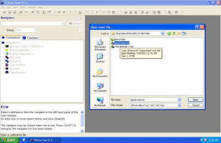
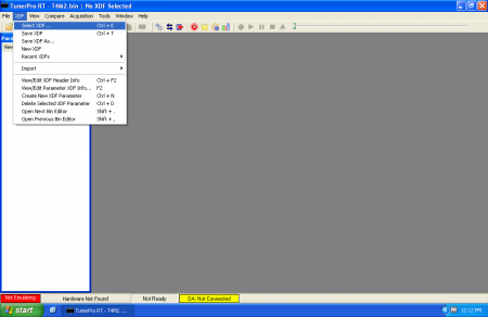
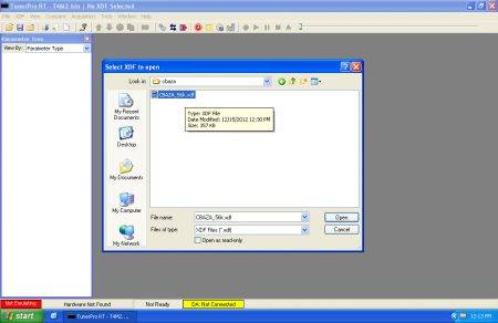
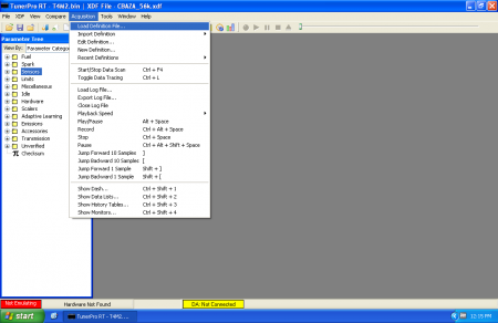
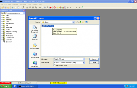
Fire up TunerPro RT.  Go to the “Acquisition” menu and choose “Load Definition File” and pick a compatible ADX.

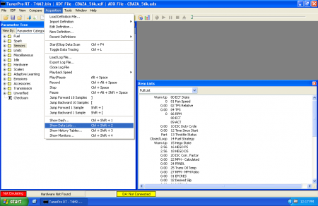
Then, “Acquisition… Edit Definition” and click the + next to “Values”

tprt adx wideband1
Next, choose the value that matches wherever you have the wideband hooked up (EGR, O2, etc.)  If the value isn’t yet defined, keep reading but understand that you’ll need to track down all the information that would be on the page.  (This generally involves talking to the person who wrote the definition or getting your hands dirty writing one)

tprt adx wideband pick a value
The crucial information on this page:

  • Title (not circled, at top of page) – this is the “name” of the item that you will see in datalogs
  • Unique ID (Blue) – this is a unique identifier for TunerPro.  It has no meaning other than being required to be UNIQUE among all Values you define.  NO DUPLICATES!!!
  • Packet Offset (Red) – this is where the value is located relative to the beginning of a data packet, or group of values retrieved at the same time
  • Source Data Size (Orange) – this is how many bytes TunerPro should look for in the packet at the Offset for this piece of data.  Note: this may be different from how the ECU represents the data unless the ECU is also using a byte or multiple of a byte sized chunk.

Signed/LSB (Green) – this is information about how the data is represented.  This needs to be correctly configured for the data item by whomever wrote the ADX.

After taking note of these values, click the “Conversion” tab (Circled in Yellow in above picture)

tprt adx wideband value conversion
The conversion tab controls how TunerPro gets from the “raw” value that you’ve specified on the “General” tab with the Offset, Size, Data type and changes it into the value you actually see.  At the top, the “Equation” visible defines the math relationship between the raw data and what you actually see.  You can click the ‘Set’ button to change the equation.

You can also specify a transfer function for further conversion of data by looking up raw data within the transfer function to get a result.  This is most often used for things like Air Temperature sensors which have an extremely non-linear output that is hard to fit with a formula.  We are NOT going to cover this further but you should be aware of this function should you have a wideband with non-linear output.

At this point, you’ve seen behind the scenes of how TunerPro handles data logging.

Configuring Wideband Logging

After having a brief tour of behind the scenes of TunerPro logging, you should still be really confused about how exactly to log a wideband.  There are several ways to get a wideband outputting a 0-5v signal to work with TunerPro:

  • Edit the existing item corresponding with where the wideband is physically hooked up to use a formula that matches the scale of the wideband.  This essentially “deletes” the original senor and permanently changes it to wideband readings.
  • Create a “duplicate” item with a new unique ID that uses the same Offset, Size, Data type as the value corresponding with where the wideband is physically hooked up.  Createa formula to match the output of the wideband.  The original sensor AND the new wideband value will both be available.
  • Create a new item with a unique ID that has nothing defined in the data packet but instead uses a linked input where the input is the existing channel data where the wideband is hooked up.  The original sensor AND the new wideband value will both be available.

There are advantages and disadvantages to each of these approaches.  There isn’t just one “right” way of doing things.  Instead of trying to cover everything, we are going to cover creating a “duplicate” item because this method allows us to work with the raw sensor data when building formulas.  Arguably, this is one of the better ways of handling things because you start with RAW data from the ECU, before it has been wrung through god only knows what other formulas.   In the interest of keeping things simpler, we are going to assume that the wideband is putting out a *linear* output.  The original sensor AND the new wideband value will both be available.

Now, it’s time to gather some information:

  • Raw datalogged ECU value at 0V input
  • Raw ECU value at maximum input voltage
  • ECU maximum input voltage
  • Number of steps in ECU’s ADC.
  • Wideband AFR value at 0v
  • Wideband AFR value at maximum output voltage
  • Wideband maximum output voltage

You should be able to consult documentation to find “theoretical” values for most of these.  (Note: reality is a bitch and you may need to further tweak “literature” values).  It is generally a good guess that a raw logged value of “0” corresponds with 0 volts.  It is a good guess that the largest number able to be represented by the ADC of your ECU corresponds with 5 volts.  i.e. for a 10 bit ADC, 2^10 = 1024 but we start counting at 0 not 1 so 1023 is the maximum value.  For a 8 bit ADC, 2^8 -1 = 255.  Almost all widebands specify their AFR output at 0V and 5V but you should still carefully pay attention to how these values are specified.

At this point, it’s simple algebra…  Y = mX + b

  1. Calculate Wideband AFR range. (Wideband AFR max – Wideband AFR min).  This gives you “rise”
  2. Calculate Wideband voltage range. (Wideband spec max volts – Wideband AFR min). This gives you “run” and is usually “5.0”
  3. Calculate the ADC voltage range.  (Subtract the max ADC voltage from the minimum ADC voltage)  This is usually “5.0”
  4. Calculate the change in AFR per raw ADC tick by dividing the result from #1 by the ADC value range that the ECU can generate (i.e. 1023, 255, 4095, etc.)
  5. Calculate the corrected AFR per tick, if necessary.  If the values from #2 and #3 are not the same (common on Nissan – 5.12v max not 5.0v), you will need to multiply the AFR per ADC tick (#4) by Wideband Voltage Range (#2) divided by ADC Voltage range (#5)
  6. The equation to plug in to TunerPro to convert raw data will be (X * Corrected AFR/tick) + (AFR at 0 volts)

Concrete Example: A9L with Innovate MTX-L

In this case, we’re going to pretend that we are using an Innovate wideband with a A9L ECU.  First off, we need to create a “clone” of the channel we are going to hook the wideband to, in this case EGR Valve Position.  Look at the original:

tprt adx evp and new

Next up, we need to click “Add New Item” (circled in Red) to make a new item and fill it out with the same information as the original EGR Valve Position but with a DIFFERENT unique name.  In this example, you can see I chose a meaningful title (i.e. the name of the item you’ll see in a list while logging) and a minimal description:

tprt adx wideband clone2

In order to figure out how to set up the ‘Conversions’ tab, we need to do math.  Going back to the previous section, our answers to the important questions are something like this (with an explanation of how we know in parentheses):

  • ECU value at 0v = 0 (good guess)
  • ECU value at maximum input voltage = 1023 (10 bit ADC maximum value, knowledge of ECU hardware)
  • ECU maximum input voltage = 5.0 V (good guess, knowledge of ECU hardware)
  • Wideband value at 0v = 7.35 AFR gasoline (page 4 of MTX-L manual)
  • Wideband value at maximum output voltage = 22.39 (page 4 of MTX-L manual)
  • Wideband maximum output voltage 5.0v

Armed with this information we can do math:

  1. Max AFR – Min AFR = AFR range.  22.39 – 7.35 = 15.04
  2. Wideband Max spec voltage – Min spec voltage = Wideband volt range.  5V – 0V = 5V
  3. ADC Max spec voltage – ADC min spec votlage = ADC volt range. 5V – 0V = 5V
  4. AFR/tick = 15.04 / 1023 = 0.0147018572825024
  5. Result #2 and result #3 are the same so no further correction is required
  6. Equation for TunerPro RT = (X * 0.0147018572825024) + 7.35

tprt adx conversions equation

Phew.  Save.  Go log your minty fresh wideband.

Reality Bites

As was mentioned earlier, reality can often differ considerably from how things “should” be.  So far, you’ve only managed to configure TunerPro for how things “should” be.  Analog to Digital Converters are plagued with issues that affect accuracy.  (Most of them can be solved/greatly improved in the analog realm by having the ECU and Wideband grounded at the same location.)  However even with the best of installs, it’s still very common for things to not end up quite as they are supposed to.  Fortunately, there are a few simple things that you can do to try and increase accuracy:

  1. The first step is going to be to make a data item for the ADC channel the wideband is connected to that displays the “raw” channel value – this can be done by changing the item’s formula to simply “X” with no further math.
  2. Next, try to get the wideband to display the LEANEST mixture (i.e. maximum AFR) that it possibly can.  This can usually be accomplished by letting the sensor hang in free air.  When the wideband is pegged lean at its maximum voltage output, observe the raw ADC reading for the channel it is hooked up to and the reported AFR of the wideband.  It is not uncommon for the voltage from the wideband to fall a few tenths of a volt (and corresponding ADC tick difference) short of the theoretical maximum voltage.
  3. Next, try to get the wideband to display the RICHEST mixture (i.e. minimum AFR) that it possibly can.  This can usually be accomplished by flooding the sensor tip with a torch (doesn’t have to be lit), CO2 / argon bottle, etc. to displace ALL oxygen.  When the wideband is pegged rich to its minimum voltage output, observe the raw ADC reading for the channel it is hooked up to and the reported AFR of the wideband.  It is NOT uncommon to see a couple tenths of a volt (and the corresponding ADC ticks) in the form of a ground offset.
  4. Compute the difference between the observed minimum and maximum ADC values.  It will likely be less than the “theoretical” maximum, i.e. 255, 1023, 4095, etc.  Re-calculate the slope based on (Displayed AFR Max – Displayed AFR min) / (observed ADC max – observed ADC min)
  5. This process boils down to the same thing as the “paper” version above but instead of making assumptions about how things “should” be you are taking measurements of how they really are.  Using “real” values versus theoretical values can often make the values you log match more closely with the values on the gauge.

OBD1 GM: Getting Started

$
0
0

Intro

This is intended to provide a brief overview of the steps required to get up and running tuning an OBD1 GM vehicle.  It is deliberately vague.  Instead of providing an exhaustive guide here, there are a series of links to smaller tasks and explanations.  94-95 LT1 vehicles are going to be an exception not covered by this guide as they are tuned via reflash only.  See the 94-95 LT1 getting started page for more.  The “What do I need GM” section is going to have basic hardware and software suggestions for groups of vehicles.

Steps

  1. Install chip adapter.  The particulars of this will depend on which chip adapter you have exactly
  2. Plug in Moates devices to your PC.  With most modern operating systems, FTDI USB drivers should install automatically via Windows Update.  In the event things don’t go smoothly, look at the USB troubleshooting guide.
  3. Download and install tuning software.  TunerCat OBD1 Tuner And TunerPro RT are the usual candidates.  This guide will cover TunerPro RT
  4. Download XDF, ADX as appropriate for the vehicle you are working on.
  5. Read your stock chip using a BURN2 or APU1 to get your stock bin OR download one online that should work
  6. Load appropriate files in TunerPro:
    • XDF first: Select XDF (this is a map of the tables and parameters to edit in a bin)
    • ADX second: Acquisition… Load Definition (this is a guide of how to communicate with the vehicle and retrieve data)
    • BIN third: File… Open (this is the actual file that goes on the chip, in the ECM, running the vehicle)
  7. Configure TunerPro to log:
  8. Get the program you want in the ECM
    • Option A: Burn a chip with the BURN2 / APU1
    • Option B: Realtime tuning
      • With Ostrich2 you will need a SocketBooster for 24 pin applications!
      • 32 pin applications work best with Ostrich2
      • APU1 works for 24 and 28 pin applications with no additional adapters
      • After you have loaded a valid BIN file, disable checksum.  To do this, change the Mask ID from it’s “normal” value (i.e. $8D hex or $6E hex or $0D hex or $42 hex) to $AA (that is “AA” in hexadecimal).  This will allow you to make changes live without angering the computer.  CRITICAL.
      • After you have a checksum-disabled bin, press the blue “up arrow” to load your bin form TunerPro to hardware
      • If you want changes to happen as you make them in TunerPro, click the blue “chip” icon near the arrows to enable or disable emulation.  You should see the status in the lower left change to indicate emulation is active
  9. Start logging.  Click the two arrows pointing away from each other.  If TunerPro can connect, you should see the lower status bar change to say “DA: Connected” along with how fast it is receiving data packets in Hertz.
  10. Tune the vehicle.

Final Words

If you have prior tuning experience with other products, you may want to look at this article which discusses the differences between more modern tuning systems and TunerPro RT on OBD1 GM.

If you don’t have prior tuning experience, you are highly advised to do some serious reading on thirdgen.org’s DIY PROM board and gearhead-efi.com to get up to speed a bit.


Transitioning to tuning older pre-OBD vehicles

$
0
0

Introduction

A substantial portion of the folks that contact us these days aren’t totally new to tuning.  The vast majority have worked with other tools before.  HP Tuners, EFI Live, Diablosport, SCT, Sniper, Cobb are some common names I hear.  I’m going to lump all of these tools together (even though they’re very different) and collectively call them “new car tools.”  I’m going to lump TunerPro, Binary Editor and EEC Editor together (even though they’re very different and Moates doesn’t actually make any of them) into another group and call them “our tools.”  This article is going to make huge, sweeping, blatant generalizations about the differences between “our tools” and “new car tools” in an attempt to help someone who has used “new car tools” better adjust to using “our tools.”

Automation: There is NONE

The first and most important difference between “new car tools” and “our tools” is the level of automation that happens.  “New car tools” are comparatively automatic: they’re designed so that you can plug in (usually to the diagnostic port), press a few buttons and have a tune in front of you to start modifying or logging.  You don’t need to know what type of ECM you’re working with.  You don’t need to know which operating system or software is installed on it.   All of these important identifying tasks happen in the background behind the scenes before a shiny list of parameters is ever presented to you. Using “new car tools,” you can be largely oblivious to what the editor you are using is doing behind the scenes.  You also have little control over how these background tasks are performed because they happen behind the scenes with little to no input from you.

This does not happen with “our tools.”  All of “our tools” are flexible applications that support multiple types of ECUs, just like “new tools.” Except there is NO AUTOMATION to speak of.  In order for you to be able to do anything useful, you need to MANUALLY configure the application to do what you want instead of having things automatically unfold in front of your eyes.  Understand that many of the same things happen in both cases but you have to be the director when using “our tools.”  To illustrate this, we’re going to dissect the process of loading a file to tune in different tools and see how they do much of the same thing in totally different ways.

Loading a Tune File with “New Tools”

efilive-open1

“File…  Open tuning file” looks innocent enough.  Pick your file then click “Open”


efilive-open2

EFI Live automatically configures itself after opening a file

EFI Live automatically detects the operating system, VIN, transmission type and more!  It automatically loads a template or definition to let you make changes to this file.  It automatically lists whether some of the important calibration controls such as Flex Fuel, Active Fuel Management, etc. are enabled.

From the moment it is done loading the file you point it to, you’re instantly ready to go. (fine print: assuming it is compatible with the file you have shoved at it.)

Loading a Tune File with “Our Tools”

tprt-open1

“File… Open Bin…” looks a lot like EFI Live did.

Things start off looking pretty similar…

tprt-open2

After opening a BIN (Tune file), TunerPro displays more or less a blank slate.

The similarities pretty much stop there.


tprt-xdf1

You have to manually load an XDF


tprt-xdf2

Choose which XDF


tprt-xdf3

With an XDF Loaded, you can edit defined parameters

The steps of loading and selecting and XDF which must be performed manually in TunerPro in order to be able to edit parameters without using the hex editor.  Datalogging is not much different: you must manually configure TunerPro to log what you want it to log.

tprt-adx1

Acquisition… Load Definition File…

tprt-adx2

Select an ADX that matches the platform you are working with

tprt-adx3

Observe the list of defined parameters in the ADX

Even after loading the right BIN, XDF and ADX files, you’re still not done!  TunerPro can operate in several different modes depending on which type of hardware you have and how you’re trying to use it.  Don’t forget to go into the Preferences and set things to suit the hardware you’re trying to use,

tprt-preferences

You will need to suit the preferences to suit the hardware you have

Why So Different?

The first thing that should stand out to you is how incredibly ‘simple’ it was to load a tune with “new car tools” compared to the many steps involved with loading a tune in “our tools.”  There are equal numbers of steps in both cases – but many of them happen automatically behind the scenes with “new tools.”  In the examples of using “our tools,” the bin file (that ends up on the chip) along with an associated definition file (XDF, ADX, “Strategy file”) have to be loaded manually.  This gives you both more control over how the process happens and more chances to screw things up.


Troubleshooting: HULOG/CROME datalogging issues

$
0
0

Intro

While it may look simple, getting the Honda logging cables we sell to work with CROME can be quite challenging.  This document aims to provide troubleshooting steps to ensure you get up and running.  Drivers and ports on your laptop, CROME settings, chip contents and ECU hardware all come into play.  “HULOG” and “Hondalog” will be used interchangeably in this document to mean the FTDI based cables and adapters we have sold.

ECU Hardware Preparation

Three things must be done to your ECU for the Hondalog to work:

  1. A 4 pin male header must be installed (“CN2” in most cases).  This occupies pins 1 – 4 of a 5 pin header presen on the ECU.
  2. A jumper that controls logging must be removed.  This is J12 on US/Euro “big case” ECUs and J4 on JDM “small case” ECUs.  Failure to remove this jumper will prevent proper communication.
  3. The ECU must be chipped!  As of writing (June 2016) there are no programs available that will log with stock ECU programs.  You must chip the ECU in order to change the way it communicates.

Drivers and Ports on Your Laptop

The Hondalog is a USB -> TTL converter that looks like a legacy serial port called a COM port to your computer. Your computer talks to it like it is a serial communications port. It uses either the FTDI FT232R or FT232A (old versions only) chips. Either way, all models use the FTDI drivers. If you are running Windows 98, 2000 or XP you probably want to use these drivers. If you are using Vista, you may want to consider using the latest drivers published by FTDI, which you can find here.  If you are running W7, W8, W8.1 or W10, chances are you are running the latest WHQL drivers Windows could download off the internet.  Most of the time, the latest WHQL drivers will work fantastic but alternate older versions of the VCP Driver are available from http://www.ftdichip.com

The first step towards getting your Hondalog working is to get it to appear as a COM port in device manager. Make sure your cable is plugged in to one of your computer’s USB ports.  To open device manager, you can usually right click on My Computer (either on desktop or in start menu) and then choose properties. Then click the hardware tab, then click the “Device Manager” button. Give it a few seconds to start, especially on older computers. Once you have device manager open, scroll down and click on the “Ports” section. You may see a few ports built in to your computer listed. Plug in the Hondalog adapter. You should see an addition COM port appear labeled “USB Serial Device” which is your Hondalog cable.  If you have more than one or you aren’t sure which belongs to your cable, unplug and re-plug the cable.  You should see a COM port appear and disappear along with the cable being plugged in.

If this does not happen:

  1. A device with a yellow exclamation mark next to it has a problem. You can click properties to find out more information, but Windows generally doesn’t give you very useful information. Most of the time, a device in this state has driver issues. Try reloading the drivers.
  2. If you get a “Unknown Device” with a yellow exclamation mark that appears elsewhere, you probably do not have any drivers installed.  Try reloading the drivers.
  3. If you get a red “x” by the icon for your device, you have disabled the device. Right click on the device and select “enable” to restore it to functioning.
  4. If you are still having trouble, take a look at this guide which goes into a little more detail about how to resolve USB issues.
  5. You can also contact Moates support.  Make sure you have an internet connection and your laptop+cable handy when you call please.

If you have gotten this far, I am going to assume your Hondalog is connected to your computer and it is being correctly detected as a COM port. I am going to assume that your Hondalog is on COM3 for the remainder of this document. You need to substitute the port that your device uses if it is not COM3!

(Note: If your device grabs a COM port greater than 16, some software seems to struggle. In fact, some software struggles with a port above 8! Bottom line: if you are having trouble and your device uses a COM port greater than 8, right click on the device in device manager, select properties and then advanced settings to change the COM port to an available port less than or equal to 8 before continuing.)

Configure CROME

CROME free does not log.  CROME Pro/Dealer is required.  We do not sell it – contact xenocron.com or tunewithcrome.com if you require a license.

CROME Pro does not automatically do anything.  You need to go into its settings and tell it three important things for logging to work:

  1. Which COM port it should use to communicate with the ECU
  2. How fast it communicates (Baud Rate)
  3. Which protocol (language) it should try to speak.

You should know the answer to #1 from your trip through device manager above.

As for #2, baud rate should always be 38400 unless you know better, in which case you can ignore this advice.

Number 3 gets trickier.   The selection here must match the contents of your chip!

  • As a rule of thumb, the QuickDLRTP.js and addDatalogging.js scripts included with CROME need the QD2 protocol.
  • As a rule of thumb, the CROME “Gold” ROM uses the QD3 protocool.
  • Non-Pro/Dealer versions of CROME sometimes fail to apply the datalogging scripts properly.  Why?  I don’t know.  Perhaps to be tricky?  Beware of doing this!
  • Beware! Some versions of the datalogging javascript make changes to how the ROM operates for fuel/ign as well as just adding logging.  Why?  I don’t know.  Double check your tune after applying any scripts.
  • There have been several versions of the datalogging scripts which set the ROM up for logging.  It is often hard to tell which is which because there is little or no version control and the scripts are sometimes encrypted/obfuscated.  Unfortunately, it matters which version is present in a ROM.
  • DIFFERENT VERSIONS OF CROME EXPECT DIFFERENT SCRIPT VERSIONS!  Do NOT use scripts from prior versions of CROME.  Be prepared to start with a stock ROM and re-apply the logging scripts in order to get logging working with a current/new version of CROME.  Even if your ROM once worked with the QD2 protocol and CROME is configured for a QD2 protocol now does not mean it will work now.
  • There have been totally broken versions of CROME.  Make sure you are using an up to date version and check on the pgmfi.org forums to make sure other users are having success with the version you are using.

***IMPORTANT!!!  IT DOES NOT MATTER WHICH PROTOCOL YOU WANT TO USE.  IT MATTERS WHICH ONE IS INSTALLED IN THE CHIP/OSTRICH***  If you did not make your chip, you need to talk to the person who did to find out what they did.  If the adddatalogging.js plugin was not installed, you’re not logging.  Bottom line: you need to know what is in your chip to know what to select.  The end.

ROM / BIN Modifications

As noted above in the section on configuring a protocol, CROME cannot speak to a factory Honda bin.  They do not speak the same language.  If you are using an unchipped ECU, it must be chipped.  If you are using a chipped ECU, these instructions apply equally to those using a physical chip and an Ostrich (or even a Demon/Demon II).  Specific modifications (in the form of the AddDatalogging.js, etc. scripts in CROME) are needed to prepare a ROM to communicate with CROME.

Again, IT IS IMPERATIVE THAT THE ROM YOU ARE USING BE MODIFIED WITH A COMPATIBLE DATALOGGING PLUG-IN!  DO NOT ASSUME THAT YOUR BIN HAS THE RIGHT SOFTWARE BECAUSE IT WORKED WITH AN EARLIER VERSION OF CROME!!!

If you aren’t sure, start with a stock bin, re-apply the logging patches, remove the checksum and bring over your changes from the old tune.

OBD1 GM Commercial Tuners

$
0
0

About

When Moates.net started, virtually all of our customers were people buying the tools we made for themselves and their own car.  All of our products were shipped blank and tunes were loaded on them by the purchaser.

Since then, things have changed.  There are nore shops and tuners out there that are using our products to tune their customers’ cars.  There are a lot of people that are looking for the results that our products can deliver without necessarily having any interest in learning to tune cars themselves.  On this page, you can find a list of shops, tuners and people that use our products for tuning cars where you should be able to get a tune together with Moates hardware or pay for help tuning Moates hardware you already have.

If you would like to be listed here, you can do so by simply emailing support@moates.net with a request.  Please include your name and/or business name, how people should contact you (website, email, phone, etc.) at a minimum.

Important Note

The individuals and shops on this page are not vetted or screened by Moates.net in any way.  The only qualification for being listed here is that we know they offer tuning services for OBD1 GMs or they’re asked nicely to be listed here.   Please do not interpret those listed here as being qualified or endorsed.  You should do your own homework before seeking the services of individuals on this page.  Think of this as craigslist not angieslist. 🙂


OBD1 GM Tuners


Minnesota/Chaska: TPI Specialties – www.tpis.com

Nevada/Reno: Scott Hansen – Tuned Port Induction Programming Services – www.scotthansen.net

North Carolina/Randleman: Brian Harris – Harris Performance – www.tbichips.com

North Carolina/Mooresville: Alvin Anderson – PCM Of NC – www.pcmofnc.com

Ohio/Cincinnati: Solomon Kostelnik – LT1 PCM


93 TBI Trucks with 4L80E transmission 16147060

$
0
0

Introduction

This is one of the first electronically-shifted transmission applications.  Some 1993 vehicles came equipped with 4L80E transmissions and 16147060 PCMs.  This is a P4 generation ECM which speaks ALDL at 8192 baud and have removable “memcals.”  This was a one-year PCM which was followed by the 16168625 / 16197427 in later years.

Hardware for Tuning

  • G1 Chip adapter and C2 27SF512 chip required to reprogram ECM
  • BURN2 Chip Programmer programs 27SF512 chips
  • ALDU1 with CABL1 required for datalogging
  • Ostrich2 required for real time tuning
  • APU1 AutoPROM All-in-one device works great, taking the place of BURN2, ALDU1+CABL1 and Ostrich2

Software for Tuning

These computers can be kind of tricky.  the $85 mask was the original but it was replaced with $D8.  You’ll need to read the memcal using a HDR1 to determine exactly which mask you have OR download a known starter bin to use from gearhead-efi or other sources.  Be warned: software support for this setup is not anywhere near as complete as the later $0D/$OE masks which followed.

$85 information page on gearhead-efi

$D8 information page on gearhead-efi

TunerPro RT + definitions from gearhead-efi works for editing and datalogging.  (this is the recommended software.  It is included with the AutoProm)

TunerCat OBD1 tuner with the appropriate definition works for editing.

Recommended Hardware to Buy

  1. G1 + BURN2 + C2 = most basic
  2. G1 + BURN2 + C2 + ALDU1 w/ CABL1 = basic with logging capabilities
  3. G1 + APU1 = Chip tune / realtime tune / datalog – full capabilities
  4. G1 + APU1 + wideband = full capabilites with wideband logging

Countries We Do Not Ship To

$
0
0

Unfortunately, there are certain countries we no longer ship to.  This is usually a result of excessive fraud or lots of packages being lost in transit.

If you order from one of these countries, your order will be refunded.

  • Phillipines
  • Myanmar
  • Indonesia
  • Malaysia
  • Cambodia
  • Laos
  • Vietnam
  • Thailand
  • Nigeria
  • South Africa
Viewing all 191 articles
Browse latest View live


<script src="https://jsc.adskeeper.com/r/s/rssing.com.1596347.js" async> </script>