Quantcast
Channel: Moates Support
Viewing all 191 articles
Browse latest View live

94-95 (ish) Mass-Air trucks with E40D Electronic Transmission AHACA Strategy

$
0
0

Introduction

94-95 MAF Trucks are an interesting breed.  They feature sequential fuel injection, a distributor for spark delivery, Mass-air flow (MAF) sensors for air metering and most importantly are set up to control an E4OD electronically-controlled automatic transmission.  Aside from their original application, these ECMs are commonly used for speed density->MAF conversions on speed density trucks and Broncos that had E4OD transmissions.   With little more than programming, they can use used to run everything from a 460cid big block (or larger) to a simple 302 or a 5.8L Windsor engine.  All of the ECMs in the name of this article use the AHACA strategy/operating system, all run E4OD transmissions and can be considered functionally equivalent for tuning.

BIO0 (F5TF-12A650-BYA) AHACA
AKC0 (F8TF-12A650-NA) AHACA
MOB1
MOB0

Hardware for Tuning

  • QuarterHorse – integrated device brings unique functionality to the table.  It is a “chip on steroids” that allows you to make changes while the vehicle is running and (with supporting software) log live data from the vehicle.  Any tunes developed using a QuarterHorse can be programmed to F3/F8 chips for long term use. (please keep reading below!)
  • F3 – simple chip module that can store one or two tunes and switch between them while vehicle is running.  Requires Jaybird programmer or BURN2+FA.
  • F8 – fancy chip module that can store eight tunes and switch between them while vehicle is running.   Can also be programmed while installed – no need to remove chip to reprogram it.  Requires Destiny programmer
  • BURN2 + FA + FE – generic chip programmer with Ford adapter (FA) and ECM interface (FE) that can be used to read the current program from EECIV and EECV ECMs on the bench.

Software for Tuning

The AHACA strategy is used on these ECMs.

  • Core Tuning definition (available through Coretuning.Net or ben@coretuning.net ) – uses same standards for organization as other Core Tuning defs, very complete, includes full datalogging. Approximately $495 INCLUDES QuarterHorse hardware!!!
  • EEC Editor ($20 available from Moates.net) has basic editing support for the these ECMs.  EEC Editor is a basic application for tuning Fords.  There is no logging support at this time. (1/2015)

Recommended Combinations

Looking at what’s available, there are 2 combinations that make sense:

  1. EEC Editor ($20) w/ WAY1 def, Jaybird ($75), F3 ($60)
    Option 1 gives you the cheapest way to tune your EC<.  You will NOT have logging – just editing.  You will NOT have realtime tuning – you’ll have to shut down, program chip, reinstall chip each time.  EEC Editor is a very basic application without many graphics or frills but it’s mostly functional as an editor.  (you can download it and check it out from the Tuning Software section of our website)
  2. QuarterHorse tuning package from Core Tuning definition ($495) and optionally Jaybird+F3. Core Tuning provides a “one stop” shop experience, directly through them.  Their definitions are generally really well laid out, well defined and have a large selection of parameters to choose from.  They’re a US company with great support.  Again, chip tuning hardware is optional but recommended.

Troubleshooting: Switches

$
0
0

Introduction

Many of our products have physical switches on them to change device behavior.  Unfortunately, we’ve noticed quite a few problems related to these switches.  Over time, sometimes switches fail to behave as you would expect them to.  We suspect this is due to oxidation on the contacts, dust or another slow-acting cause.


Affected Devices

These devices use the switches which are known to have issues:

  • AutoProm / APU1
  • Ostrich2
  • ALDU1


Solution

Fortunately, the solution to switch glitching is really easy.  Sliding the switch back and forth vigorously 5-10 times has been successful in restoring normal operation.

QuarterHorse: Battery Installation

$
0
0

Currently shipping QuarterHorses differ from the original in two subtle ways:

  1. There is a circuit to keep the QH’s memory using power from the Keep-Alive-Memory voltage supplied to the ECM with the key off. This should decrease the amount that the QH’s own battery is used in cars regularly driven.
  2. The BR2331A solder-on battery has been replaced with a socketed CR2032 removable battery. (commonly available)

This version of the QH is shipped without the battery installed. You should install it prior to use.

1. Open bags and unpack everything. You should have a loose battery along with a QuarterHorse module:

Quarterhorse and battery unpacked

Quarterhorse and battery unpacked

2. Turn the battery so the “+” side is facing up. Slide it under the metal spring end of the battery holder.

First, slide the QH under the metal clip side of the battery holder

First, slide the QH under the metal clip side of the battery holder

3. Push the battery gently downwards and toward the metal spring. The end of the battery opposite the metal spring should slide under the brown plastic retaining clip and lock into place.
done
4. Once installed, the brown plastic clip will hold the battery pretty tightly.  Should you need to replace it, the easiest way to remove the battery is to gently pry on the metal clip with a small screwdriver until the battery clears the metal retaining clip and can be gently pulled out.

94-95 (ish) Mass-Air trucks with 4R70W Electronic Transmission CBAZ0 Strategy

$
0
0

Introduction

Some 94-95 Trucks (mostly F150) came equipped with a 4R70W automatic transmission.  Most of the heavier-duty trucks came with AOD-E transmissions and use incompatible ECMs.  These ECMs feature sequential fuel injection, a distributor for spark delivery, Mass-air flow (MAF) sensors for air metering and most importantly are set up to control a 4R70W electronically-controlled automatic transmission.  These ECMs can be used to run the combination of a pushrod V8 and 4R70W.   Ideal for those wanting to run a mode modern electronically controlled automatic transmission instead of an AOD with a pushrod engine.  With little more than programming, they can use used to run everything from a 460cid big block (or larger) to a simple 302 or a 5.8L Windsor engine.  All of the ECMs in the name of this article use the CBAz0 strategy/operating system, all run 4R70W transmissions and can be considered functionally equivalent for tuning.

BUG0
BUG2
GET0
GLO0
GLO2
HUG0
HUG2
JAB1
L4J1
P5X0

Hardware for Tuning

  • QuarterHorse – integrated device brings unique functionality to the table.  It is a “chip on steroids” that allows you to make changes while the vehicle is running and (with supporting software) log live data from the vehicle.  Any tunes developed using a QuarterHorse can be programmed to F3/F8 chips for long term use. (please keep reading below!)
  • F3 – simple chip module that can store one or two tunes and switch between them while vehicle is running.  Requires Jaybird programmer or BURN2+FA.
  • F8 – fancy chip module that can store eight tunes and switch between them while vehicle is running.   Can also be programmed while installed – no need to remove chip to reprogram it.  Requires Destiny programmer
  • BURN2 + FA + FE – generic chip programmer with Ford adapter (FA) and ECM interface (FE) that can be used to read the current program from EECIV and EECV ECMs on the bench.

Software for Tuning

The CBAZ0 strategy is used on these ECMs.

  • Core Tuning definition (available through Coretuning.Net or ben@coretuning.net ) – uses same standards for organization as other Core Tuning defs, very complete, includes full datalogging. Approximately $495 INCLUDES QuarterHorse hardware!!!
  • Binary Editor ($100 / $171 available through Moates.net) combined with Derek Fenwick’s CBAZ0 definition ($25, contact sailorbob@uk2.net directly to obtain) supports these ECMs.  Usually complete and extremely functional.
  • EEC Editor ($20 edit / $25 log available from Moates.net) has basic editing support for the these ECMs.  EEC Editor is a basic application for tuning Fords.  Logging support is experimental.

Recommended Combinations

Looking at what’s available, there are 3 recommended combinations:

  1. EEC Editor ($20) w/ WAY1 def, Jaybird ($75), F3 ($60)
    Option 1 gives you the cheapest way to tune your EC<.  You will NOT have logging – just editing.  You will NOT have realtime tuning – you’ll have to shut down, program chip, reinstall chip each time.  EEC Editor is a very basic application without many graphics or frills but it’s mostly functional as an editor.  (you can download it and check it out from the Tuning Software section of our website)
  2. QuarterHorse tuning package from Core Tuning definition ($495) and optionally Jaybird+F3($75+$75). Core Tuning provides a “one stop” shop experience, directly through them.  Their definitions are generally really well laid out, well defined and have a large selection of parameters to choose from.  They’re a US company with great support.  Again, chip tuning hardware is optional but recommended.
  3. QuarterHorse ($249), Binary Editor ($100) with Derek Fenwick definition ($25) and optionally dongle for BE ($+71) and optionally Jaybird+F3($75+$75)  Binary Editor is better software.  Derek generally makes very good definitions.  The combination of QH + BE + Def is going to give you realtime tuning while the vehicle is running AND datalogging to see engine and transmission parameters.  It’s still a good idea to have a chip for long-term use but chip tuning hardware is optional, at least from a getting started perspective.

G2 Adapter Installation

$
0
0
G2
G2 TBI-Style 2732-to-29C256 Adapter Installation Instructions:Here is a pictorial depiction of a G2 installation in a TBI-style ECM.
It shows the following:

1) Disassembly and removal of stock socket body.
– Take note of the ‘stock’ 2732A chip orientation. Your 2732A chip will probably be in a little plastic holder.
– Try and overcome the challenge presented by the disparity between that fact and this pictorial guide.
– Take apart the ECM case, loosen screws that hold ‘daughterboard’, and get everything free so you can get to the underside.
– Be careful with ribbon cables which are often glued to the ECM housing areas.
Measure spacing between row of chip socket pins, and make sure you order the correct adapter part (0.6 or 0.45″).
– Using small screwdriver, gently pry plastic off of pins. It should come free, leaving pins to be desoldered individually pretty easily. This may not work as well with 0.45″ spacing sockets, and you might have to desolder the whole socket at the same time or mutilate it a little bit to get it out.

2) Desoldering of stock socket pins, removal of solder from holes using solder sucker.
– Apply heat and remove each individual pin (assuming you were successful with step (1).
– Use solder sucker to open up each hole for acceptance of the ‘new’ socket.

3) Soldering in place of a 24-pin collet-pin DIP socket. (For 0.45″ spacing, 12-pin SIPs are used instead).
– Just like it says. If you want a very low profile install, skip this step and go to step (4), except solder it in place instead of pressing it in.

4) Placement of G2 adapter along with optional ZIF and associated chip.
– Just like it says.

5) View of relative clearance and reassembly.
– Check and make sure it’s not going to hit anything when installed back in the car. If you have clearance issues, you might want to consider the solder-in option mentioned in (3-4).

Note that the height can be reduced by not using the ZIF socket, and can be further reduced by soldering the adapter directly in as mentioned (bypassing the DIP or SIP socket install).

These pictures should give you the information you need with respect to procedures, relative socket / adapter / chip orientation, etc.
However, if after viewing this you still have questions, just let me know at my email address on the main page and I’ll do my best to field them.

Have fun!

HDR1

$
0
0
HDR1
Instructions for using the ‘HDR1’ Memory Header

The HDR1 memory adapter is primarily designed to download the existing code from a stock Memcal.
It can be used for other things as well. For instance, if you want to use a UV eraser on your stock Memcal and then reprogram it without tearing stuff up, the HDR1 allows this to be done very easily.

Step 1: Take the stock Memcal (or whatever) and identify where the pins come out for the existing EPROM.

Step 2: Insert the HDR1 into the Memcal and note the orientation of the existing chip.

Step 3: Place the assembly into your favorite chip reader / programmer (AutoProm shown, chip notch facing ZIF handle, empty spaces nearest to handle).

Step 4: Go ahead and read or re-program the chip.

That’s it! No mess, no fuss. Pretty straightforward.

G3/GP3 Configuration and Use

$
0
0

The ‘G3’ Switching Adapter

(also: Using the ‘EX’ with the G3)

Note: This product was updated in 2015.  The original documentation (which still applies) follows with a discussion of differences between the original and current hardware.

For placing several different binaries on a single chip for GM applications, the G3 adapter is the hot ticket. By ‘stacking’ the binaries on a large-sized memory, and using the included switching ability, you can swap between different programs on-the-fly while the car is running. You could have ‘Valet’, ‘Economy’, ‘Nitrous’, or whatever else you want to put together.

First a little background. A memory chip is accessed by changing the state of various connections or pins. Some of the pins are called address lines. They tell the chip which data to present. There are low address lines (A0 through A14) and high address lines (A15 through A18). The larger chips like the AM29F040 have A0-A18, or 19 address lines. What the G3 adapter does is take ‘manual’ control of the address lines A15-A18. If you study binary stuff, you’ll know that this will give you 16 different memory ‘banks’ which can be selected.

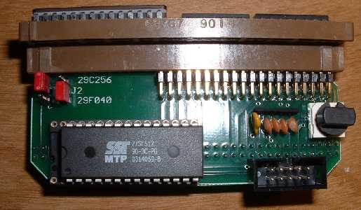
On the G3 are several components, including one thermofuse (looks like a capacitor) to protect against shorts when using the ‘EX’ module, four capacitors which help dampen RFI pickup from the EX cable, two jumpers to set the operating modes (see below), and a rotary DIP switch to select which bank of memory is to be accessed.

Installation instructions for the G3 adapter are very similar to those for the ‘G1’ adapter, so see the section under ‘G1’ instructions for guidance in this regard.

Think of the G3 as an old-style channel selector on a TV. You just turn the knob, and the car’s ECM will see a different channel or ‘bank’ of memory. Put the switch to position zero, and all the ‘high’ address lines will be set to 5v. Thus, the actual memory location that will be accessed on a 29F040 will be 78000-7FFFF. If the switch is set to position ‘F’, then all the high address lines will be set to GND, or ‘low’. In this case, the reference memory will be 00000-07FFF. You can see how this lets you put up to 16 programs on a single chip and select between them. The switch positions are numbered 0-F, which is just hexadecimal for zero through 16.

There are several different hardware configurations which are possible with the G3. This increases flexibility along with the confusion factor. Let’s look at these combinations individually:

1) Putting a 29F040 chip in the G3, and operating with an ECM that originally takes a 27C128 (16k bin) or 27C256 (32k bin). This gives you 16 bins.
2) Putting a single 29C256 or 27SF512 chip in the G3, operating in ‘passthrough’ mode with no switching.
3) Putting a 29F040 chip in the G3, and operating with an ECM that originally takes a 27C512 (64k bin). This gives you 8 bins.
4) Putting a 27SF512 chip in the G3, and operating with an ECM that originally takes a 27C256 or 27C128. This gives you 2 bins.

The most typical cases are (1) and (2), so we’ll talk about them first.

For operating instructions on the ‘EX’ module, see the bottom of this page.

Case 1: Originally a 27C128 or 27C256, use a 29F040 chip to switch between 16 programs.

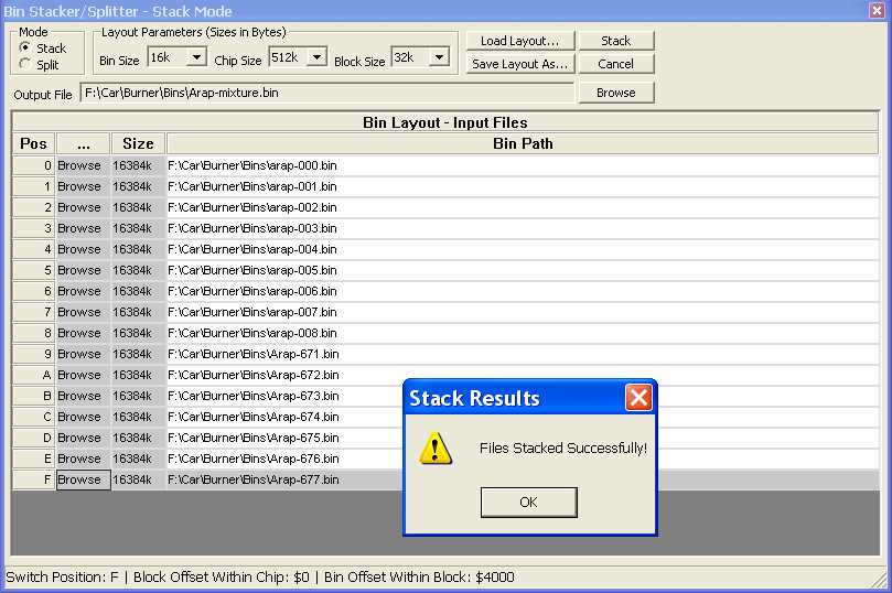
First thing you will want to do is ‘assemble’ your big 512k binary from a group of smaller ‘stock-size’ binaries that you create or collect. The screenshot shows the configuration screen in ‘TunerPro’ under the BIN stacker function whereby the proper settings have been selected.

Notice how the bin size here is 16k (originay a 27C128) and the chip size is 512k (for a 29F040). The switch size for the Case-1 hardware configuration is 32k. This is going to create a 512k fie that you can then burn directly to a 29F040 chip without any offsets. Also note that TunerPro does the BIN order reversing for you, so all you need to worry about is which switch position is associated with which BIN.

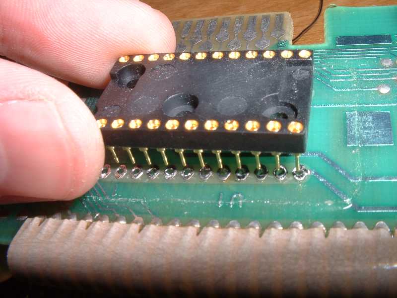
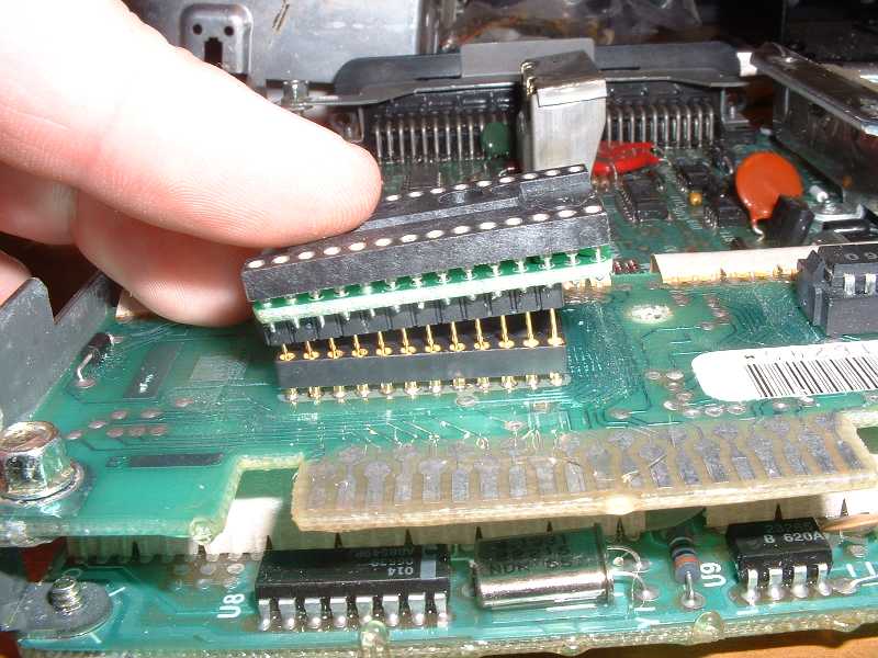
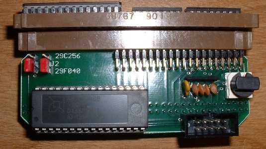
The jumper positions for this Case-1 are such that both jumpers should be placed in the ‘down’ position as shown in the picture. This will allow full access to a 29F040 chip’s memory banks via the switching with bank sizes up to 32k. Make sure the notch on the chip is facing to the left as shown.

Case 2: Originally a 27C128, 27C256, or 27C512 chip, use a 29C256 or 27SF512 chip as a single-program pass-through application.

If you want to use the G3 as just a straight adapter and not a switcher, this can be done very easily. Just program the chip as you normally would for a single-program application and put it in the adapter.

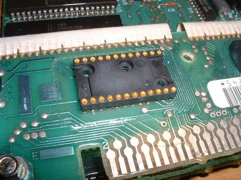
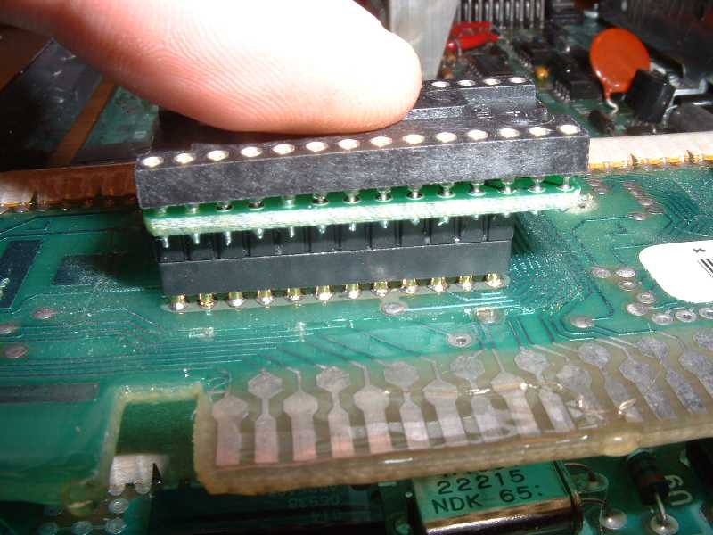
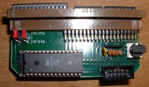
Only trick is to make sure that you set the jumpers to the ‘up’ or 29C256 position. This will allow the G3 to act just like a ‘G1’ adapter, passing the signal directly through and bypassing the switching functionality. Make sure the chip is moved over to the right, with the notch facing left.

Case 3: Originally a 27C512 chip, use a 29F040 chip to switch between 8 programs.

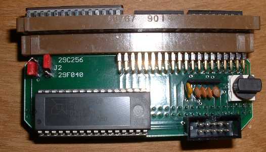
Now we’re getting to some more ‘flexible’ appication of the G3. For this case, the jumpers should be set as shown, with J1 in the ‘down’ or 29F040 position and J2 (right) in the ‘up’ position. You still stack your BINs using the TunerPro Bin Stacker, but the settings should be such that your Bin Size=64k, Chip Size=512k, and Switch Size=64k.

When switching in this mode, there will be a little difference. In this mode, position 0-1 are the same and 2-3 are the same and so on. So, in terms of which BIN you will be accessing, you’ll be seeing BIN0 in positions 0-1, BIN1=2-3, etc through BIN7=E-F. This gives you 8 binaries you can put on the chip and select from, with a switch occurring every ‘other’ switch position.

Case 4: Originally a 27C128 or 27C256 chip, use a 27SF512 chip to switch between 2 programs.

OK, so you don’t want to run 16 different binaries? Just two? Here’s an option for you. Set up your BIN in TunerPro again, with the Bin Size=16 or 32k, chip size=64k, and switch size=32k. Set the jumpers with J1 in the ‘up’ position and the J2 in the ‘down’ position. This will allow the A15 line to get switched every other switch position.

When operating in this mode, the first bin will be accessed at switch positions 0,2,4,6,8,A,C,E and the second BIN will be accessed in the other positions. This gives some switching flexibility without the confusion of millions of binary files.

That’s about it in terms of G3 operation. Again, the installation is pretty much the same as for the G1 so see that section for instructions in that regard.

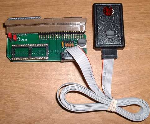
Using the ‘EX’ module:
The function of the ‘EX’ module is that of a remote BIN switching device and display indicator. When used with the G3, the ‘local’ G3 rotary switch should be placed in the ‘0’ zero position!

If you want to have a ‘AntiTheft’ or ‘Valet’ mode, you should put that binary in position zero, so you can disconnect the EX and carry it with you. It can be unplugged from the ribbon cable at any time. Don’t worry about plugging it in backwards. It won’t short out, it just won’t work right and won’t light up. If it lights up with the car on, you’ve got it right.

Revisions of the ‘G3’ Switching Adapter

As of 2015, there are two different versions of the G3 Adapter.

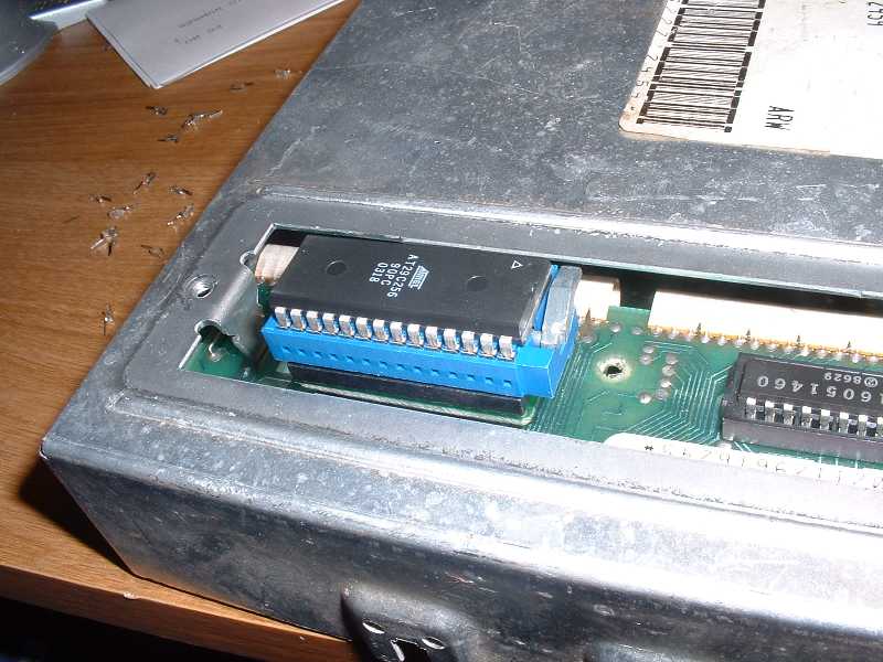
The first version has a rotary switch on board and a single 10 pin connector.  This is the version that this article has discussed so far.  It was manufactured up to 2015:

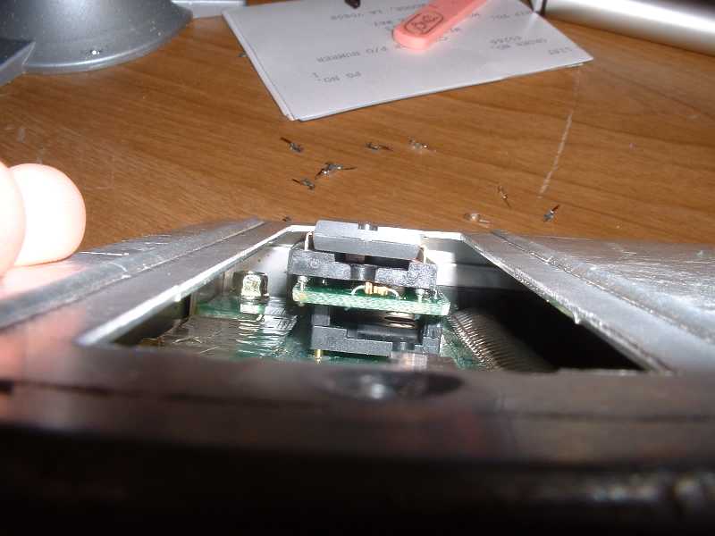
The second version does NOT have a rotary switch.  Instead, it has two connectors – one 10 pin (like before) and a provisoin for a 4 pin (new, open not installed in this picture).  It was manufactured starting in 2015:

G3 New 2015

Fortunately, they function nearly identically.  The new version is simplified with fewer configuration steps required due to having fewer jumpers.  Both versions can be used on the same platforms for the same thing – allowing multiple programs to be used on OBD1 GM vehicles.

  • The early version can be used for switching without any external hardware via the knob.  The current version requires either the EX remote (which connects to the 10 pin connector) or a rotary switch with 4 pin cable.
  • The current model only switches three address lines allowing a maximum of 8 programs, regardless of the program size.  Earlier models supported switching more address lines in some configurations
  • The current model will only function in pass-through mode for a single program when using a 28 pin chip.  The previous model could support switching between two 32k or 16k programs with a 28 pin 512k chip.
  • The current model has only one jumper which selects whether a 28 pin 27SF512 chip or 32 pin 29F040 chip is installed.  The earlier model had a second jumper which selected the program size.  The only jumper that needs to be adjusted on the new model is to select which chip (27SF512 vs 29F040) is installed – the current version will always function as if J1 was set for 64k operation.
  • The current model always presents 64k chunks of memory, i.e. if J1 on the earlier model was set for a 64k block size.  The earlier model could present smaller chunks, the current model only presents 64k chunks.  When using 16k or 32k bins with the current G3, ensure they are arranged in the top section of a 64k block.

Honda Tuning with Crome Tutorial

$
0
0

Although quite outdated, this is a very nice PDF tutorial written up by Darren Kattan. Check it out by clicking HERE


HULOG/HondaLog Installation

$
0
0
Hulog/Hondalog
Installation of Honda-Based USB Datalogging Tools

There are two tools available for datalogging on Honda ECUs from www.moates.net and they include the HULOG and the HondaLog.

HULOG: The HULOG comes in a plastic enclosure and ONLY requires a pin swap if it is an older unit. All the new units come with 1:1 connector pinning, so will differ from the pictures shown in that no pin swap is required or will be present on the extension cable. It can be mounted externally or internally, depending on whether you want to pass the 4-pin header cable or a USB cable out of your ECU.

HondaLog: The HondaLog can be mounted directly to the ECU with no interconnecting cable It can also be mounted at the end of a 4-pin tether cable. Either way, no pin swap is required (note color of wires and their order in the pictures). The unit is shipped with two pinning options in terms of the attachment header. It also comes with a piece of shrink-wrap tubing in case you want to ‘wrap that rascal’ when you’re done. Either way, it goes to your USB cable and PC on the other end.

Pictures are shown below for the two units. The installation header is a 4-pin latching unit, and comes with the moates.net Honda Chipping Kits. You can alternatively use a 4-pin 0.025″ square-post breakaway header. Please take note of the directionality of the latch on the interconnecting cable though, since that is critical.

HULOG Pictures


HondaLog Pictures


Bluetooth Install on Ostrich

$
0
0
Bluetooth
For the Ostrich2, the following will show you how to install the Bluetooth into the unit:
1) Open the Ostrich (two screws), keep track of the two nylon spacers.
2) Gather up the Bluetooth kit parts as shown in the pictures below.
3) Place the pin headers on the Bluetooth module and snap them on, and then solder it in place as shown.
4) Screw the unit back together (no cleaning necessary) and connect using Bluetooth software (separate tutorial available).
For the original Ostrich, look here:
Ostrich BT Install Pictures
Basically, it is as follows:
1. Remove jumper caps and install shielded angle header.
2. Install module.
3. If you want to go back to USB, then REMOVE bluetooth module and you can put the jumper caps back in place.

Honda Chipping Kit Install

$
0
0

This is Keebler65’s old guide. Some of the chipset and software info is a bit dated, but the techniques are good.

ECU Chipping

You need to add a few additional components to the original Honda ECU. It requires some soldering skills and should not be attempted unless you have soldered before. (Chances are you know someone with soldering skills that could help you). Here is a picture of the P28 ECU that I chipped, before any of the parts were put in:


Before you can solder the parts in, you will need to de-solder the holes in the circuit board since they come filled with solder from the factory. You can buy a “solder sucker” to do the job, however unless you get a nice one (expensive) they don’t really work well in my opinion. The cheap and easy solution is to buy some solder braid. It’s just braided copper. Simply place it over the hole to be de-soldered, and place the soldering iron on top of the braid. It will then wick up the solder into the braid. It’s available at radioshack:


You’ll want to use a decent quality soldering iron to get the job done nicely. The important thing is to not use too much heat, and also make sure the iron has a fine tip on it. I’m using a standard Weller iron:


Here is what it should look like after the board has been de-soldered:


The parts that need to be added are boxed in with a dashed white line. The parts consist of (2) .1uF ceramic capacitors, (1) 1k resistor, (1) wire jumper (simply a piece of wire…I used a lead of the resistor), (1) 74HC373 chip, and (1) 29C256 chip (thats the EPROM). The resistor and capacitors have no polarity, so you don’t have to worry about installing them backwards. The 74HC373 chip does have a polarity. Pin 1 will be on the left side of the pic (you’ll see in detail later one). The same is true for the EPROM chip. Since it would be impossible to burn a chip and have the tune be perfect, it becomes obvious that you don’t want to solder the chip in. Instead, use a socket so that it can be removed. You have two options: for less than $1, you can get a standard DIP socket. The problem is these are very hard to insert and remove the chips since there are 28 pins (it requires a lot of force and is hard to grip the chip). Your second option would be a ZIF (Zero Insertion Force) socket, which costs less than $10. It is a socket that has a lever: pull up the lever, set the chip in/lift it out, and flip the lever back – VERY nice to have since you’ll be doing this many times while tuning. Be careful when ordering the ZIF socket, as many of them are too large to fit on the board without running into things. The first ZIF I bought was made by Aries, and it was a very quality piece, however, it was too large and bulky to fit without a lot of modification to other components on the board. I ended up ordering a different one that was much more compact. I am unaware of the brand, however it is blue and is referred to as a low-profile ZIF. The only problem was that the lever end of it was in the way of the 74HC373. The easy solution is to buy a standard DIP socket as mentioned above. Solder this onto the board. Then, stack the ZIF onto this socket, which raises the ZIF away from the board enough to clear the surrounding parts. This setup worked very well for me. The following picture shows the too-big-to-fit ZIF in the back-left, the low-profile ZIF in the front left, and the DIP socket on the right:


The ZIF socket stacked on the DIP socket for added height:


And finally, a couple of pics with all of the parts installed:


I ordered most of my parts from www.jdr.com except for the low-profile ZIF socket and DIP socket, which I obtained from www.jameco.com. The following table containse the exact part numbers that I ordered. You’ll notice that I ordered two EPROMS. This way, it will be easier to burn one while the other is installed.

Part Number Quantity Description Source
29C256-12PC 2 This is the chip that you burn with Uberdata JDR
74HC373 1 The other chip that is reqired JDR
R1.0K 1 1K resistor JDR
.1UF 2 .1uF capacitors JDR
102744 1 Low profile ZIF Socket Jameco
40336 1 28 Pin DIP socket Jameco

Additionally, I have recently located all of the parts you will need from one source. DigiKey is where you can find them. Their inventory selection can be overwhelming, so here are the part numbers you will want:

Part Number Quantity Description
AT29C256-70PC-ND 2 This is the chip that you burn with Uberdata
MM74HC373N-ND 1 The other chip that is reqired
1.0KEBK-ND 1 1K resistor
478-4279-3-ND 2 .1uF capacitors
A347-ND 1 Low profile ZIF Socket
A409AE-ND 1 28 Pin DIP socket

And for a final update to this page, I’d like to add that you can find ALL of the necessary chipping parts at moates.net. It is a great deal in my opinion, and you’re guaranteed to get the correct parts the first time around. It’s under the name of “Honda ECU Chipping Kit”.

Ostrich 1 Operation

$
0
0
Ostrich
Here’s how you install the Ostrich:  (Much of this will apply to the Ostrich 2 as well but pictures will be different.)

1) Get on the website here in the ‘software and drivers’ section and download and unzip the ‘USB Drivers’ file. Remember where you put it.

2) Plug the Ostrich into the USB port of your PC, and point the operating system to the previously located USB Driver directory and install the drivers. See the USB Driver Installation Guides here on www.moates.net for further guidance in this regard.

3) Go into the drivers and set the COM port of the USB to Serial Converter (under Ports in the Device Manager of the Windows Control Panel). Set it to COM3 or COM4. Override any warnings against ‘port in use’ or any of that nonsense. Again, refer to the USB install guides for more info.

4) While in the port settings, set the latency to ‘1’ (default=16). This will speed it up dramatically.

5) Use TunerPro RT or a similar program to upload a binary to the Ostrich, and verify that it is uploaded correctly.

6) Hook it up to the vehicle, and go to town. When installing the ribbon cable where the chip normally goes, orient the red stripe so that it faces where the chip notch or arrow (pin #1) would normally face.

Note: If you have the car off, and the Ostrich is hooked up to the car’s ECU, then sometimes an upload/verify won’t work right. Just turn the car on, or disconnect the Ostrich during the initial upload, and everything should be fine.

There are jumpers inside the Ostrich, depending on how many pins / memory size you are emulating to.
The following pictures illustrate three different ones: 24, 28, and 32-pin. The 32-pin is only used for Ford EEC-V applications right now.

24-pin (with associated pictures for an installation where the original chip was a 2732A in a 1227747-style GM ECM):
Here’s the jumper settings, set for 24-pin emulation:

Here’s the socket that is soldered in the ECM. Note the direction of the notch (to the right) indicating where the original chip pin #1 would go:

Here’s one way to do it, first right before insertion and then after it is snapped down in. Really it is preferable to use a ZIF socket here. Notice the 24-pin socket that is stacked onto the bottom of the regular 28-pin emulation cable. You can just use the 28-pin with the extra 4 pins hanging over as well. Note the red stripe toward where the notch would normally go:

28-pin Installation using the G1 chip adapter, similar to that used in a 1986-92 TPI GM ECM:
Check out the jumper settings. Note that this is the configuration that the Ostrich is shipped with, and works for the majority of the applications.

Note the direction of the notch on the chip, despite the direction of the ZIF handle. This is counter-intuitive for many, and is relatively unique to the G1 / TPI-style adapter due to spatial constraints in the ECM housing:

Now we take the chip out, and put the emulation cable in. Note the red stripe and how it is oriented compared to the notch on the chip that was there before:

32-pin Jumper Settings, presently only used for EEC-V applications:

O-Meter

$
0
0
O-Meter
The O-Meter’s physical dimensions are 2.500″ x 1.625″ x 0.800″Check out the documentation to understand what all this unit can do! Does AFR/Lambda/Universal display, data storage, etc. Fully user configurable through two easy-touch buttons. Available in red (brighter) or blue (not as bright but looks cool!). Blue is a little more because of the parts cost.

Here is the instruction guide for the O-Meter so you can read about all the features:
http://static.moates.net/zips/ometer_guide.pdf

Here is a video of the O-Meter in action:
http://static.moates.net/zips/ometer_1.mpg

Here are pictures of how to hook up the wiring between the O-meter and the LC-1:

http://static.moates.net/gallery/ometer_wiring/

Demon

$
0
0

demon1

Introduction / Identification

The Demon (or original Demon, Demon 1) pictured above  is the first of our integrated devices aimed at Honda/Acura-friendly P28/P30/P72 OBD1 ECUs. Flawless realtime emulation, embedded datalogging, auxiliary ports, 16x calibration storage and encryption.   The Demon is designed to fit inside both USDM and JDM ECUs including those with knock boards.   The Demon combines the features of the Ostrich, Hulog, RTP, and adds its own unique feature set.  The Demon requires software to specifically support many of its features – not all software support is equal.

Ports and Connectivity

The Demon uses the same FTDI Device drivers as the rest of the products that we sell.  The Demon a USB mini-B port for internal cable connection.  Plugging a cable from the Demon to your PC will allow your PC to communicate with the unit.
The Demon supports additional devices through the black 4 pin add-on header, which is an option to install.  Some examples of devices that can be used are the TunerView II, TunerView RD1 and BlueTooth serial modules.   When using the 4-pin TTL with devices such as the Demon/Tunerview interface, TunerView RD1, or Bluetooth, be SURE that the pinout is:
Demon1: 1=TX out, 2=RX in, 3= GND , 4= 5V out
***IMPORTANT***  The original Demon and Demon II **DO NOT** have the same pinout!  It is entirely possible for damage to occur if incorrectly pinned peripherals are plugged in to the Demon!  ***IMPORTANT***
Please make sure you have the correct cables to support the hardware you have.  If you have any doubts, please contact us.
If your Demon did not come with the auxiliary port installed, the following picture illustrates the correct orientation of the 4 pin right angle connector:
demon1bt_aux

Software Support

As of 11/03/09 software support is as follows:
Neptune: Full emulation+data+onboard (release)
ecTune: Emulation+data (release)
Crome: Emulation+data (beta)
Please note that each Demon has a serial number – NepTune and eCtune both license a single copy of the software to a single Demon.  The exact procedure for this is different for each software package.

Datalogging Memory

The first production runs of Demons have 1 Mbyte memory for storing datalogging.  Current (starting around April 2010) production units have 4Mbyte memory.  Early production units can have their memory upgraded.  If you are interested in this service, purchase the Install Service item and note in the “Comments” field of your order that you would like the Demon memory upgrade.  You’ll have to send your Demon back to us – turnaround time is normally about 2 weeks.

Switching Between Software

You can now more easily switch among the different applications using our Config Utility for resetting the state of your Demon.

Indicator Lights (1.8 and older firmware)

The Demon has two LEDs to indicate its status, one red and one green.

The red LED serves as a hardware status indicator and/or busy light.  It can come on when:

  • Demon is currently processing a command (upload/download/etc)
  • Poor / nonexistent connection between Demon and ECU 28 pin socket.  (usual cause: faulty installation)
  • Poor / nonexistent connection between Demon and ECU CN2 port.  (usual cause: cabling, cable backwards, faulty installation)
  • Demon is powered via USB but there is no power to ECU
  • NEPTUNE RTP ONLY: No serial communication between ECU and Demon
  • Red LED will blink when onboard packets are being stored to memory

The green LED is more of a data packet and status indicator light.  It typically behaves as follows:

  • Lights up solid green when the Demon is powered on
  • Blinks when the Demon is communicating with the ECU (assuming data packets are configured correctly)
    • Fast blinking means data is flowing properly from ECU to Demon via CN2
    • Slow blinking likely means data timeout / incorrect connection/configuration


Indicator Lights (1.9 and newer firmware)

Light behavior has been changed in the new firmware.

The red LED serves as a hardware status indicator and/or busy light.

  • Red light on solid = not receiving power from the ECU: physical connection issue to ECU
  • Red LED will blink when logging packets are being captured

The green LED is more of a data packet and status indicator light.  It typically behaves as follows:

  • Solid green light when the Demon is powered on and all systems are go but no packets are being received
  • Green light is off when the device is busy OR Demon is powered off
  • Fast green blinks mean the Demon is receiving good datalogging packets from the ECU.

Troubleshooting:

  • Red light onwith USB plugged in means the Demon is NOT receiving power from the ECU.
    • You will only see this condition when the Demon is being powered by USB
    • Check 28 pin socket bridge pins and connection
    • Check ECU CN2 – 4 pin port connection.  This is REQUIRED for proper Demon operation
  • Green light off means no power to ECU.  Red on / green off is expected with no power.
  • No lights at all when USB is plugged in generally is a fault condition.
    • Try removing the Demon from the ECU.  If the Red light comes on, check the chipping job and physical connections between the Demon and the ECU

EmUtility: standalone emulator control

$
0
0

Introduction

Ever wish your favorite Moates emulator would work with your favorite ROM editor software that doesn’t have native support for our products?  EmUtility (from the author of TunerPro) allows you to use Moates emulators with any software that can spit out a binary (bin) or hexadecimal (hex) format file.  It supports the Ostrich1, Ostrich2, APU1 *and* RoadRunner!  It can even support more than one emulator connected to the same computer simultaneously. (this requires more than one instance of the program, one for each emu)

Installation

You can get EmUtility from the Utilities section of TunerPro.net

EmUtility may require additional files to be installed for it to work, specifically the Microsoft Visual C redistributable libraries, which  are also linked off the Utilities section of TunerPro.net

EmUtility does not come with an installer – it is shipped as a zip file with a single program file inside.  Unzip it to place where you will be able to easily find it, such as your desktop.  You can run it directly from the desktop and it will not make a “mess” because it is only one file.

Usage

EmUtility is pretty straightforward to use.

First, start the program.  You should see “Detecting Hardware… Ostrich 2.0 blah blah blah” for instance.  If you see “No Hardware Detected” check your cables and connections.  If you cannot get your hardware to detect, try looking at our USB Troubleshooting Guide.

After you have verified that your hardware has been detected properly, click the “…” next to “Input / Output File” to select a file to use.  (If you are going to read the contents of the emulator to a file, this can be a new file)

Next select an operation from the drop down box next to “Operation”  Valid operations include:

  • Read from emulator to file = creates a new file on your computer with the contents of emulator RAM.  Must specify a filename, how much memory you want read (size), if you want to use a non-standard start address (File Start Address)  and if you want to use large RAM support (required for files > 512kbit / 64k byte)
  • Write from file to emulator = updates the RAM on your emulator with the contents of a file on your computer.  Must specify a filename  and if you want to use large RAM support (required for files > 512kbit / 64k byte).  File size and start address will be automatically selected for you and will be correct in most cases where your file is the same size as the chip you are trying to emulate.  (i.e. 32k byte file for 27C256 chip)
  • Verify emulator RAM with file = compares the contents of the Emulator’s RAM with a file on your computer to see if they match.  Must specify a filename  and if you want to use large RAM support (required for files > 512kbit / 64k byte).  File size and start address will be automatically selected for you and will be correct in most cases where your file is the same size as the chip you are trying to emulate.  (i.e. 32k byte file for 27C256 chip)
  • Monitor File for changes and upload = this operation monitors a file for changes and uploads the changes to your emulator as they happen. ust specify a filename  and if you want to use large RAM support (required for files > 512kbit / 64k byte).  File size and start address will be automatically selected for you and will be correct in most cases where your file is the same size as the chip you are trying to emulate.  (i.e. 32k byte file for 27C256 chip)

After you have selected and configued the operation you desire, click “Execute” to perform it.  To cancel a monitoring+upload session or other op, click “Cancel Op”

That’s it!

Suggested Uses

If you have a program that can spit out bin files but it does not support Moates hardware:

  1. Start EmUtility
  2. Pick “Write from file to Emulator”
  3. Point EmUtility at the file you are working with
  4. Click “Execute” to load the initial file
  5. Change the operation to “Monitor file for changes and upload”
  6. Click “Execute” to begin monitoring the file for changes
  7. Leave EmUtility running in the background.  Go back to your editing application.  Make changes and save the file (with the same filename).  As you save changes to the file, EmUtility will copy them to your emulator almost instantly!

Nissan 16 bit applications with TunerPro 4.x: (using a daughterboard like our Nissan 20×2 that takes two identical chips and two Ostrich 2.0 emulators)

  1. Plug in ONE Ostrich and follow the directions immediately above to set up monitoring for an application that does not support Moates hardware.
  2. Leave EmUtility running and connect the second Ostrich.
  3. Start TunerPro.  It should detect your second Ostrich.
  4. Start your emulation session in TunerPro.
  5. Tune away.  TunerPro will update one Ostrich, EmUtility will update the other

(Note: TunerPro 5.x supports dual Ostrich mode which is easier to set up than this)

16 bit Nissan applications such as 925style.com’s ROM  EDITOR (using a daughterboard like our Nissan 20×2 that takes two identical chips and two Ostrich 2.0 emulators)

  1. Plug in ONE Ostrich and follow the first set of directions above to set up monitoring for an application that does not support Moates hardware.
  2. Leave EmUtility running and connect the second Ostrich.
  3. Start a SECOND COPY of EmUtility.  It should detect your second Ostrich.
  4. Repeat the instructions for loading a binary and starting monitoring in the second EmUtility session
  5. Tune away!  As you save changes to the file, each instance of EmUtility will update one emulator.

Using the RoadRunner as a general purpose 16 bit emulator with software that does not have native support (i.e. Bosch Motronic 28Fxxx):

  1. Start EmUtility
  2. Pick “Write from file to Emulator”
  3. Point EmUtility at the file you are working with
  4. Click “Execute” to load the initial file
  5. Change the operation to “Monitor file for changes and upload”
  6. Click “Execute” to begin monitoring the file for changes
  7. Leave EmUtility running in the background.  Go back to your editing application.  Make changes and save the file (with the same filename).  As you save changes to the file, EmUtility will copy them to your emulator almost instantly!

Who uses our gear?

$
0
0

This page is being created so we have a place to keep track of all the people who are using our gear for various applications.  If you would like to be added or removed from here, please email support@moates.net or leave a comment.  Hit control-F to find keywords on this page as eventually we hope this grows to a very large list!

ECU Connections forum – mostly Bosch Motronic stuff.

DS-MAP – MAP sensor conversion for DSM ECUs, supports Ostrich

TunerPro RT – general purpose ROM editor that supports APU1, Ostrich, ALDU1 and most of our gear.  Useful for Nissan, Ford, GM, DSM, some Bosch Motronic (BMW, Porsche, VW, etc.) among others. (we sell this)

ThirdGen.org – forum dedicated to the 3rd gen camaro/firebird with a great Tuning section!

EFI Live – Supports our RoadRunner Emulator for OBD2 GM vehicles (we sell this)

Binary Editor – Supports our QuarterHorse emulator for 86-04 Ford vehicles (we sell this)

EEC Editor – Supports our QuarterHorse emulator for 86-04 Ford vehicles (we sell this)

TunerCat – supports APU1, ALDU1, Ostrich, etc. for OBD1 GM vehicles

Neptune – supports Demon, Ostrich, BURN2,  etc.  The premiere solution for tuning 92-01 distributor Hondas (we sell this)

eCtune – supports Demon, Ostrich, BURN2, Hondalog, etc.  Another great 92-01 distributor Honda solution

Crome – supports Demon, Ostrich, BURN2, Hondalog, etc.  an older and poorly maintained 92-01 distributor Honda solution

TurboEdit – supports Ostrich, Hondalog.  an old and finicky software package for 88-91 distributed Hondas

BRE – supports Ostrich, Hondalog.  an old and finicky software package primarily aimed at 89-91 Vtec hondas

Pgmfi.ORG – Home of the DIY Honda community.  Birthplace of CROME, TurboEdit, BRE and loosely affiliated with other softwares.  Still a great resource for Honda ECU tuning.

Nistune – supports Ostrich, dual Ostrich.  Nissan ROM tuning software, dealer version works with our hardware.  Programs made with Nistune work with our Nissan 2Chip adapter.

Tuning Porsche 944 turbo vehicles using TunerPro, Ostrich, SocketBooster (thanks Joshua)

Turbo Mopars using Ostrich2

RhinoTuning using Ostrich2 / BURN2/ etc. for tuning Suzuki Swift pre-OBD2 vehicles

Nissan Data Voice uses the Ostrich2 for realtime tuning for OBD1 Nissan vehicles

Ford: Box code – strategy – vehicle cross reference

$
0
0

This page is intended to help people who have looked here to figure out if there is support for their vehicle.

Each ECM has a 3 or 4 digit processor code that uniquely identifies it.  You can tell what strategy a ECM uses from its box code or from looking at a dump of a stock program from that ECM.  “Strategy” is Ford’s lingo for a program to run a vehicle. (or operating system)  Each strategy can have multiple calibrations for different engines.  Sometimes even V6 and V8 engines will use the same strategy!

If you are wondering if your strategy is supported, take a look at the Supported Strategies guide.

This list will grow over time.  If you don’t see your vehicle listed here, email support@moates.net

A9L = GUFB (88-93 “Fox body” V8 mustang 5-speed)

A9P = GUF1 (88-93 “Fox body” V8 mustang auto)

T4M0 = CBAZA (94-95 SN95mustang  5.0 V8)

LLX4 = CDAN4 (96-97 Cobra 4.6L 32v)

PTP2 = FBFG2 (04 Mustang GT)

RCX5 = CDAN4 (97 Tbird 3.8L v6)

SLL4 = CTBAE (96 5.0 explorer ??? )

LKT3 = ODAJ0 (02 F150 4×4 auto)

SCI1 = ODAG0 (02 F150 4×4 manual)

NMI1= ODAG0 (02 F150 4×4 manual)

MIJ1 = ODAG0 (02 F150 4×4 manual)

KVF1 = ODAL1 (02 F150 4×4 manual)

CXN1 = MNAE1 (01 Lightning)

CUX1 = MRAD2 (01/02 Lightning)

CUX2 = MRAD3 (01/02 Lightning)

URB1 = TAUF0 (02/03 Lightning)

There is a handy Excel spreadsheet you may want to look at ( link ) that has a decent cross-reference.

Tuning: MAF systems, air leaks and reversion

$
0
0

Introduction

As stated in our overview of MAF systems, one of their main weaknesses are air leaks.  Whenever air can enter the engine without going through the MAF, weird things happen.

There are two principal kinds of leaks that wreak havoc on MAF systems – constant leaks (like a unplugged vacuum port) and mechanically induced leaks (such as a Blow Off Valve or Bypass Valve that vents to atmosphere.)  Each leak has a tendency to affect the system differently.  In this article, we will try to take a look at what “should” be happening, what changes with a leak and what kind of odd things you can look for while tuning to identify a leak.

Reversion presents an additional problem for MAF systems.  Reversion is the technical name for when air changes direction and reverses flow.  MAFs are not one way systems – they will measure air flowing into the engine and then meter the same air flowing out of the engine when there is severe reversion, causing unreliable MAF readings.

Constant leaks

This kind of constant leak in a MAF system is the classic “vacuum leak” where a gasket, coupler or piece of tubing in between the MAF and the engine does not seal properly.  In this case, air can enter the engine without passing through the MAF.  Because air has entered the engine without passing through the MAF sensor, the MAF sensor reads artificially low.  An engine operating in open-loop mode will tend to run very lean.  A motor operating in closed loop will see very large positive trims as the computer uses the O2 sensors to add fuel to compensate for the lean condition.

The air leak provides more air for the engine at idle which will make the idle rise or sometimes “hunt” or bounce around unstably.  Generally, the idle system will also try to compensate.  On Fords you will see the ISC Integrator (“Integrator”) swing negative, indicating the ECM is allowing less flow through the idle valve than is commanded in the tune.  It is very common for the Integrator to get stuck at the minimum allowed value and have the car still idle higher than commanded.

Most MAF systems use the MAF for calculating appropriate timing values as well as fueling.  With a vacuum leak throwing off the system, the ECU thinks there is less air entering the engine than their really is.  This will mean that “load” values will be artificially low, which generally leads to timing being artificially high.  In severe situations, this combination of issues (less fuel, more timing) is a recipe for melting engine components if it goes unchecked.

Mechanically induced leaks

Bypass valves are the most common source of mechanically induced leaks although idle, purge and other vacuum operated solenoids can all be a problem.  MAF systems require these valves to be re-circulated so that air leaving the valve re-enters the intake AFTER the MAF so it does not get measured twice.

Blow off valves on turbocharged vehicles are often vented to atmosphere.  This unfortunately will severely confuse a MAF system.  When the valve opens, air that has already passed through the MAF and been “counted” is released into the atmosphere instead of entering the engine.  The ECU will supply enough fuel for all the air that has passed through the MAF while only a small portion of this air actually entered the engine.   This causes the engine to run very rich and can cause stalling or other problems when letting off the gas and the BOV opens.  Once the valve closes again and the car burns off the excess fuel delivered, things slowly return to normal operation.

Supercharger bypass valves can present the same kind of issues when they are allowed to vent to atmosphere. (or when there is a leak in the piping allowing air to recirculate.)  Failing to catch an air leak with a supercharger bypass will result in the MAF curve having a sudden change when the valve closes.  This will require complete re-tuning of the MAF transfer function once fixed so it is best to catch it early.

Reversion

Reversion is most common in engines with very large camshafts operating at low speeds such as close to idle.  Situations where MAFs read unreliably due to reversion can generally be greatly improved by moving the MAF further from the throttle body.  Increasing the volume of the intake between the MAF and the throttle body is also effective at smoothing out the pulses of air coming from an engine with a radical camshaft.  It is normally possible to get a reliable enough MAF signal in most circumstances.  Even extremely wild cams that draw 3-4″ of vacuum at idle can be tamed with an appropriately designed intake system.

Another form of reversion that is troublesome to MAF systems happens with poorly designed supercharger bypass valve systems.  In most of these systems, the pipe connecting the outlet of the bypass valve connects with the inlet of the supercharger at an angle where recirculated air flows backwards through the intake.  This causes any reverse-flowing air to be metered multiple times by the MAF, leading to unreliable operation.  This can almost always be remedied by adjusting the angle of the pipe from the bypass so it points at the inlet of the supercharger directing the flow of recirculated air away from the MAF.

Reversion is very obvious if you are logging the MAF signal. Looking at a graph of a “normal” MAF signal versus time, it will look like a line that could have been drawn without reversing the direction of travel.  The same graph of a MAF impacted by reversion will look very “shaky” and jagged, changing direction many times in a short period of time.

Ford Tuning: Load with failed MAF table(s)

$
0
0

Introduction / Prerequisites

Before you read this, make sure you have read Theory: Alpha-N, Theory: Mass Air Flow and the FordOverview.  Although not essential, it wouldn’t hurt to have at least read about Speed-Density operation as well.  This page will assume you have read and understood these pages.  This is a somewhat complicated topic and will require you to put several pieces together so don’t feel bad if you have to read this a couple times.

About the table and why it is critical

The “Load with failed MAF” (“LWFM” from here forward) table(s) are found in almost all MAF Ford Strategies.  Most strategies that make use of IMRCs (Intake Manifold Runner Control – valves that restrict air entering the engine in order to increase tumble and velocity) have two LWFM tables instead of one and  switch from one LWFM table to the other as the IMRCs open and close.  The main purpose of the LWFM table is to estimate the amount of air going into the engine without using the MAF sensor or a MAP sensor (if present) to provide the ECM with an “emergency” fallback method of running the engine in the event the MAF sensor fails.

The LWFM table is also important for normal operation of the motor because Load from the MAF (this is “Load” – the Ford-specific calculated cylinder filling value calculated from the MAF sensor, RPM and engine displacement) is “sanity checked” against the LWFM table to determine if the MAF is providing reliable information.  If there is too large of a difference between calculated Load and the LWFM table, the ECM may ignore the MAF even if it is providing valid information! This happens most commonly in forced induction situations (where load is greatly increased compared to a naturally aspirated car) but can also occur in cars with aggressive camshafts.  If you are making changes to a MAF transfer function and you are not seeing any changes in engine operation, double check your LWFM table!  Further, most strategies use “Anticipation logic” to predict airflow.  This prediction logic is based off…  Surprise… The LWFM table!  Having a sane LWFM table is neccesary for the aircharge anticipation logic to work.  You can disable this but it’s generally not necessary if you tune the LWFM table properly.

LWFM table is a classic example of an Alpha-N control strategy – it’s purpose is to provide a very crude estimation of airflow entering the engine when the MAF signal is absent or the ECM thinks it is unreliable.   The LWFM table uses only two inputs – throttle position (aka “TP”) and RPM to determine Load.  Here is a picture of a typical LWFM table: (screenshot from Binary Editor / GUFB strategy)

Here you can see the X axis is RPM and the Y axis is RELATIVE Throttle Position volts.  Each cell represents the Load that will be used to calculate fueling and timing when the ECM thinks the MAF is bad.  For example, idling with the throttle closed (0 volts relative)  around 700 RPM the ECM will assume a Load of .1602 and make appropriate fueling and timing changes.

The importance of the LWFM table varies considerably from strategy to strategy.  A rule of thumb is that the newer of an ECM you are using the more picky it will be able the LWFM table.  Fox Body and most early EECV (pre-99) are fairly tolerant of inappropriate LWFM tables where 99+ ECMs are generally much, much, much more picky.

Tuning the LWFM Table

Tuning the LWFM table is pretty simple:

First, set the Aircharge WOT multiplier, Anticipation logic scalars, etc. to make the ECM as tolerant of a bad failed MAF table as possible

Second, GUESS!   Yes, guess.  Enter values that you think are sane for the setup, starting with the stock LWFM table as a guideline.  A few examples:

  • If you put in aggressive cams, decrease the LWFM table at low RPMs and throttle angles while increasing it at higher RPMs and throttle angles.
  • If adding a positive displacement supercharger (roots, twin screw) multiply the whole LWFM table by approximately the highest pressure ratio you will see.
  • If you add a centrifugal blower, multiply a column of the LWFM table by the pressure ratio you achieve at a given RPM

Third, drive around and log throttle position (TP Relative), RPM, Load.  Compare the Load values you log with the LWFM table.  Start changing entries in the table so they get closer to the load you really see at given TP and RPM conditions.

Note: Turbo cars present a very big challenge to this strategy due to the amount load can vary with throttle position due to spool time.  This is a very tricky case and often the only solution is to try and maximize allowed error before the LWFM table becomes active and also disable Aircharge Anticipation and other functions dependent on the LWFM table.

BURN1+F2A+F2E: Reading Ford ECMs

$
0
0

Requirements

There are two products that we sell that can read the program in a factory ECM:

BURN1/BURN2 with a F2A and F2E – This setup can be used to read ECMs on the bench.  ECM does not need to be powered.

QuarterHorse – This setup requires the ECM to be powered either by a vehicle’s battery or a 12V bench power supply.

Reading with BURN2+F2A+F2E

  1. Start with all cables disconnected (F2A,F2E,USB,etc.)
  2. Connect the F2E to the F2A
  3. Put the F2A in the BURN1/BURN2
  4. Connect the Burn1-2/F2A/F2E Assembly to your ECM.  Make sure your ECM is powered off if it is in the vehicle
  5. Connect the USB from the BURN2 to the PC
  6. Start Flash n  Burn Software on the PC
  7. Choose appropriate settings for the Supported chip type based on the ECM type:  J3 Ford EEC-IV Reader or J3 Ford EEC-V Reader
  8. Choose appropriate settings based on the number of banks used:
    • 56k EEC-IV = 032000 start 03FFFF end
    • 64k EEC-IV = 030000 start 03FFFF end
    • 2-bank EEC-V = 010000 start 02FFFF end
    • 4 bank EEC-V = 000000 start 03FFFF end
  9. Click “Save buffer to file” and choose a filename.

Reading with QuarterHorse

At the time of writing (Aug5-2010) Binary Editor is the only software that supports this feature of the QH reliably.  Select “Read PCM” from within the software.

Viewing all 191 articles
Browse latest View live


<script src="https://jsc.adskeeper.com/r/s/rssing.com.1596347.js" async> </script>